
This section is for my current project, a custom built JAMMA arcade machine (aka Super Gun), this section will be quite fluid while the design is perfected, choices are made and materials are acquired.
Main Document
Designs
- Main box holding the PSU
- Power Voltage Dial
- LED 5v Power Readout
- Video Out (RGB, Component, Composite, S-Video), so some sort of video conversion card
- Volume Dial
- Audio Out MONO
- Audio Out STEREO (from custom JST board output)
- Audio In for stereo inputs from custom JST board outputs
- Audio Switch for MONO and STEREO (Custom or JAMMA audio output)
- JAMMA Out
- Service Switch Button (Not really required)
- Player 1 Joystick Port
- Player 2 Joystick Port
- Joystick Player 1 Design
- Player 1 Start Button & Player 2 Start Button
- Coin Switch 1 Button
- Three Player Buttons (Red, Green, Blue)
- Test Switch Button
- Sanwa Joystick (Part# JLF-TM-8T-SK-K)
- Joystick Player 2 Design
- Player 1 Start Button & Player 2 Start Button
- Coin Switch 2 Button
- Three Player Buttons (Red, Green, Blue)
- Test Switch Button
- Sanwa Joystick (Part# JLF-TM-8T-SK-K)
I've decided to make the joystick common, with Player 1 Start, Player 2 Start, Test and Coin Switch Button, then they can be used in either port, plus some games are two player but used only one joystick.
JAMMA Standard
The following information is related to JAMMA video interface standard.
Japan Amusement Machinery Manufacturers Association (社団法人日本アミューズメントマシン工業協会), often known as JAMMA, is a trade association based in Tokyo, Japan.
This is a set of standards developed for board pinouts to make changing games cheaper for arcade operators, they can swap boards rather than rewire a whole machine.
Unfortunately games evolved and the JAMMA standard is no longer up to the job, it cannot handle more than five buttons or two players, has no Stereo sound output. Newer games requiring extra player controls using molex type connectors placed on the top of the board (Street Fighter - Kick Harness etc...).
Also replacing a board from a different manufacturer meant readjusting the picture on the monitor as it would not be centred in the same position.
| Component Side | Pin | Pin | Solder Side |
|---|---|---|---|
| Ground | 01 | A | Ground |
| Ground | 02 | B | Ground |
| +5 VDC | 03 | C | +5 VDC |
| +5 VDC | 04 | D | +5 VDC |
| -5 VDC | 05 | E | -5 VDC |
| +12 VDC | 06 | F | +12 VDC |
| No Connection (Key) | 07 | H | No Connection (Key) |
| Coin Counter 1 | 08 | J | Coin Counter 2 |
| Coin Lockout 1 | 09 | K | Coin Lockout 2 |
| Speaker Positive (+) | 10 | L | Speaker Negative (-) |
| Audio (+) | 11 | M | Audio Ground |
| Video RED | 12 | N | Video GREEN |
| Video BLUE | 13 | P | Video SYNC |
| Video Ground | 14 | R | Service Switch |
| Test Switch | 15 | S | Tilt Switch |
| Coin Switch 1 | 16 | T | Coin Switch 2 |
| Player 1 Start | 17 | U | Player 2 Start |
| Player 1 Up | 18 | V | Player 2 Up |
| Player 1 Down | 19 | W | Player 2 Down |
| Player 1 Left | 20 | X | Player 2 Left |
| Player 1 Right | 21 | Y | Player 2 Right |
| Player 1 Button 1 | 22 | Z | Player 2 Button 1 |
| Player 1 Button 2 | 23 | Aa | Player 2 Button 2 |
| Player 1 Button 3 | 24 | Ab | Player 2 Button 3 |
| Player 1 Button 4 | 25 | Ac | Player 2 Button 4 |
| Player 1 Button 5 | 26 | Ad | Player 1 Button 5 |
| Ground | 27 | Ae | Ground |
| Ground | 28 | Af | Ground |
Player 1 Button 4 "25", Player 1 Button 5 "26", Player 2 Button 4 "Ac" and Player 2 Button 5 "Ad" are very rarely if ever used.
All input pins need ground to be activated (active low).
Key 7/H says no connection because there's usually a piece of plastic placed in to this spot which will line up with a slot cut in the PCB. This is to prevent any chance of the connector being connected upside-down.
Coin Counter 1 "08" and Coin Counter 2 "J" are outputs. This is for a mechanical style counter that increments every time a coin is inserted.
Coin Lockout "09" & "K" are outputs. This delivers power to a plunger activated by a solenoid which, when engaged into the coin path of the coin mech, will prevent a valid coin from tripping the coin switch and send it to the coin return slot. When power is fed to the coin door, an electromagnet retracts the plunger so that the coin path becomes open. Few games have coin lockout software in them.
Service Switch "R" puts 1 credit onto the game but does not increment the Coin Counter, used for testing games.
Test "15" enables the test mode, if the PCB supports it triggers the test mode software of the game, usually used to test the screen, sound and inputs (joystick and buttons).
Tilt "S" like in pinball games. The switch is found on almost all coin doors and is a leaf switch with a weight on the tip of one of them. If you slam the game hard enough, the leaf switch will close. Almost no games have tilt software in them. Behaviour ranges from a screeching tone for a few seconds to resetting the entire game.
Coin Switch 1 "16" and Coin Switch 2 "T" are inputs. When a coin is inserted, a Ground pulse is sent to this pin and credits the game.
Speaker +/- "10" & "L" is mono output. An external amp in not required. The speaker +/- is for post-amp output directly to the speaker.
Audio +/- "11" & "M" is for pre-amp outputs but is hardly ever used.
Looms
The design choices that have been made for the previous projects have been generally good with the choice of D-subminiature or D-sub connectors, these are quite easy to solder, readably available and quite robust in use, I will use these on the JAMMA and Joysticks connections.
- JAMMA
- Monitor
- Speaker
- Joystick
- Power
JAMMA
1M cable.
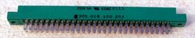
56way (2x28way) JAMMA 0.156 High Quality Edge Connector - £6.95.
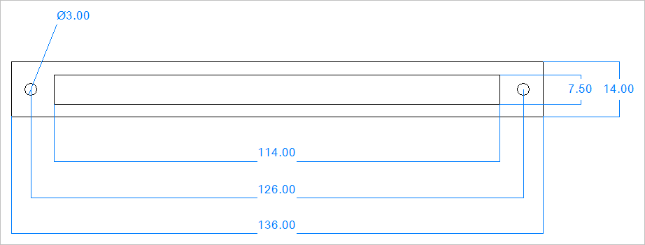
JAMMA Connector Box diagram (all dimensions in mm)
Monitor
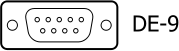
DE-9 D-sub
http://www.maplin.co.uk/Module.aspx?ModuleNo=1113
Metallised D-sub Hood, I prefer these to the grey plastic ones as these are quite a bit smaller and much better looking, they also finally make a DE-15 version which I will use on the joysticks.
http://www.maplin.co.uk/Module.aspx?ModuleNo=1128
Speaker
Arcade boards have their own audio amps and were designed to be plugged directly into a speaker, I will used Clamps or banana plugs.
A custom cable for the stereo based games (JST Connector) will also be made.
Joystick
After using a Sanwa Joystick on my last project, they are great sticks, I still don't like the Sanwa buttons and will be using HAPP buttons instead, this will be a bit of a hybrid Japanese/UK joystick. I've not made the choice on the Coin, Start or Test switches yet.
Sanwa Joystick (Part# JLF-TM-8T-SK-K).
Player 1 Start Button, Player 2 Start Button, Coin Switch 1 Button and Test Button.
3 Player Buttons (Red, Green, Blue).
Power
UK mains plug to IEC320 C13 cold kettle mains black lead, 2M.
This is the best choice as the cables are readily available UK PC power cables.
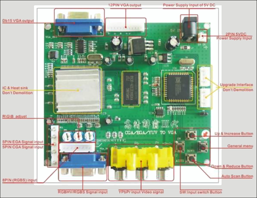
Internal Cables
Power Supply Outputs
This is a standard 16Amp arcade power supply.
| Function | Colour |
|---|---|
| +12v | Orange |
| -5v | Purple |
| GND | Black |
| GND | Black |
| +5v | Red |
| FG | Green (Earth) |
| AC 1 | Blue (Neutral) |
| AC 2 | Brown (Live) |
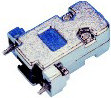
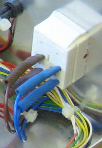
Power Switch - Illuminated
GU55K - DPST 16A Red Rocker £2.19.
Live Brown
Blue Neutral
 Solder Side of Switch
UK mains plug to IEC320 C13 cold kettle mains black lead, 2M.
Blue Neutral
Live Brown
Green Earth
 Solder Side of Socket
Joystick - D-sub
 Solder side of connector inside the Super Gun
01 02 03 04 05 06 07 08
09 10 11 12 13 14 15
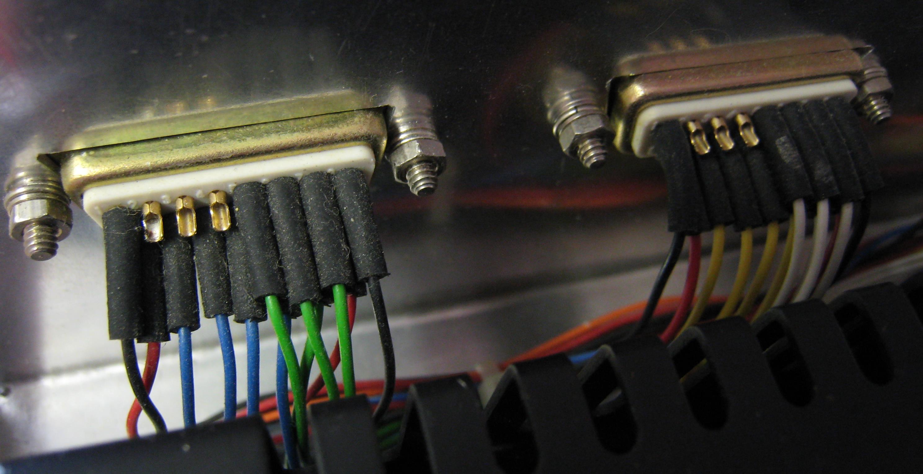
The three spare connectors have now been used for Player 2 Start (or Player 1 Start), Test Switch and Coin Switch 1 (Or Coin Switch 2).
Player 1
Right hand connector, when viewed inside (solder side)
| Pin # | Function | Multi-Core Cable | Internal Colour |
|---|---|---|---|
| 01 | Ground | Black | Black |
| 02 | Player 2 Start | Pink | Green |
| 03 | Test Switch | Yellow/Red | Gray |
| 04 | Coin Switch 1 | Light Green | Orange |
| 05 | Player 1 Button 3 | Blue | White |
| 06 | Player 1 Button 2 | Green | White |
| 07 | Player 1 Button 1 | Red | White |
| 08 | Ground | Gray | Black |
| 09 | +5 VDC | Green/Red | Red |
| 10 | Player 1 - Right | White | Yellow |
| 11 | Player 1 - Left | Purple | Yellow |
| 12 | Player 1 - Down | Yellow | Yellow |
| 13 | Player 1 - Up | Brown | Yellow |
| 14 | Player 1 Start | Orange | White |
| 15 | +5 VDC | Blue/Red | Red |
Player 2
Left hand connector, when viewed inside (solder side)
| Pin # | Function | Multi-Core Cable | Internal Colour |
|---|---|---|---|
| 01 | Ground | Black | Black |
| 02 | Player 1 Start | Pink | White |
| 03 | Test Switch | Yellow/Red | Gray |
| 04 | Coin Switch 2 | Light Green | Orange |
| 05 | Player 2 Button 1 | Blue | Green |
| 06 | Player 2 Button 2 | Green | Green |
| 07 | Player 2 Button 3 | Red | Green |
| 08 | Ground | Gray | Black |
| 09 | +5 VDC | Green/Red | Red |
| 10 | Player 2 - 1 | White | Blue |
| 11 | Player 2 - 2 | Purple | Blue |
| 12 | Player 2 - 3 | Yellow | Blue |
| 13 | Player 2 - 4 | Brown | Blue |
| 14 | Player 2 Start | Orange | Green |
| 15 | +5 VDC | Blue/Red | Red |
JAMMA - D-sub
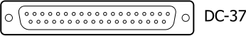 Solder side of connector inside the Super Gun
01 02 03 04 05 06 07 08 09 10 11 12 13 14 15 16 17 18 19
20 21 22 23 24 25 26 27 28 29 30 31 32 33 34 35 36 37
Note: Maplins no longer sell this connector but they can still be bought online.
| Pin # | Function | Colour | - | Pin # | Function | Colour |
|---|---|---|---|---|---|---|
| 01 | Coin Switch 2 | Pink | - | 20 | Player 2 Button 1 (Red) | Green |
| 02 | Player 2 Start | Green | - | 21 | Player 2 Button 2 (Green) | Green |
| 03 | Player 2 - Up | Blue | - | 22 | Player 2 Button 3 (Blue) | Green |
| 04 | Player 2 - Down | Blue | - | 23 | +5 VDC | Red |
| 05 | Player 2 - Left | Blue | - | 24 | +12 VDC | Orange |
| 06 | Player 2 - Right | Blue | - | 25 | Speaker Negative (-) | White |
| 07 | -5 VDC | Purple | - | 26 | Video GREEN | Green |
| 08 | Ground | Black | - | 27 | Video SYNC | White |
| 09 | Ground | Black | - | 28 | Ground | Black |
| 10 | Coin Switch 1 | Orange | - | 29 | Ground | Black |
| 11 | Ground | Black | - | 30 | Video BLUE | Blue |
| 12 | Ground | Black | - | 31 | Video RED | Red |
| 13 | -5 VDC | Purple | - | 32 | Speaker Positive (+) | White |
| 14 | Player 1 - Right | Yellow | - | 33 | +12 VDC | Orange |
| 15 | Player 1 - Left | Yellow | - | 34 | +5 VDC | Red |
| 16 | Player 1 - Down | Yellow | - | 35 | Player 1 Button 3 (Blue) | White |
| 17 | Player 1 - Up | Yellow | - | 36 | Player 1 Button 2 (Green) | White |
| 18 | Player 1 Start | White | - | 37 | Player 1 Button 1 (Red) | White |
| 19 | Test Switch | Gray | -- |
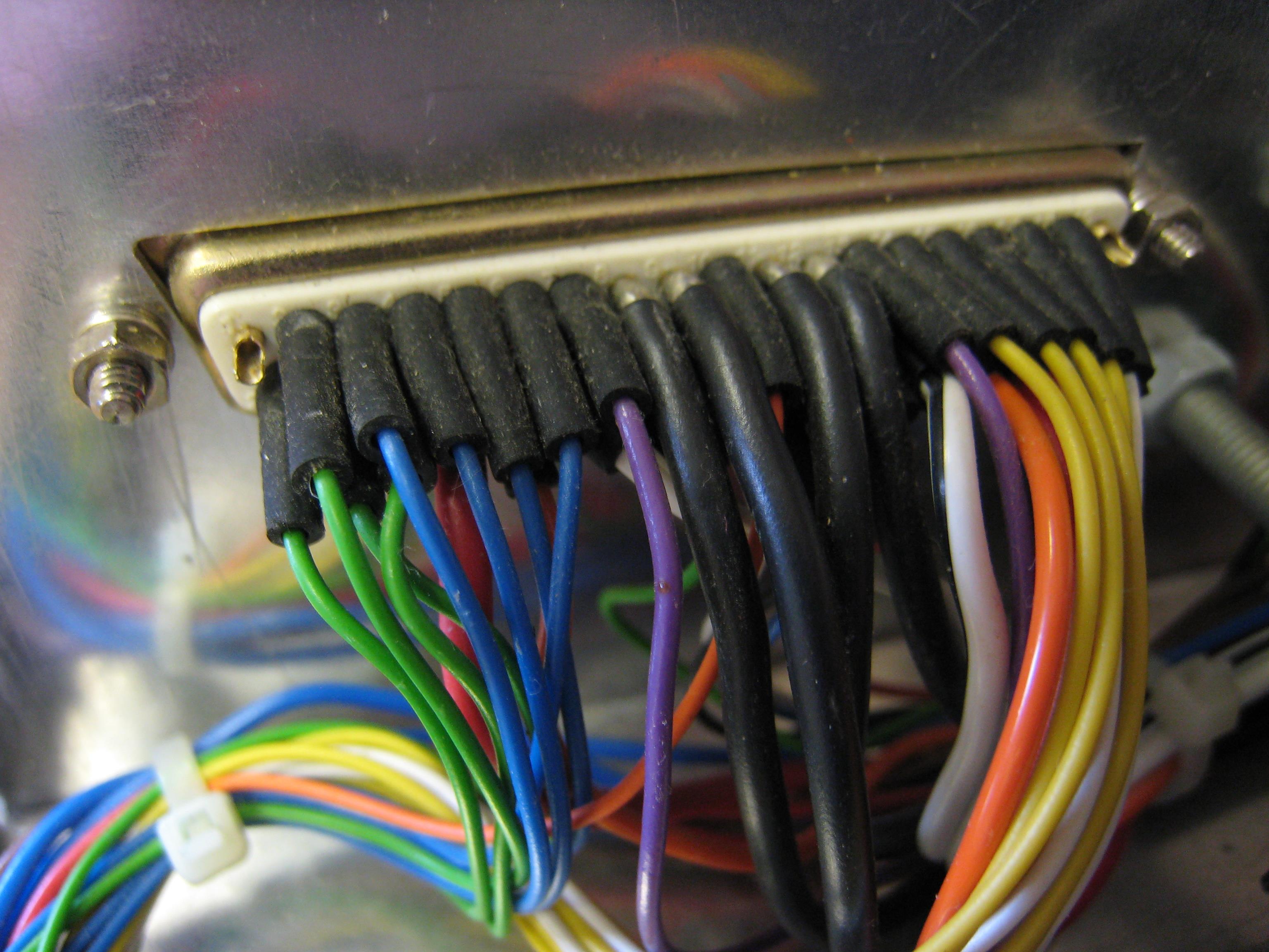
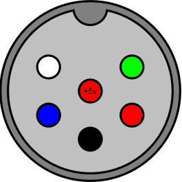
Monitor - DIN-6
I've decided to stick with the DIN-6 for the monitor connector on the system as I've found a better technique when soldering them.
 Solder side of connector inside the Super Gun
| Function | Colour |
|---|---|
| Video Ground | Black |
| Video RED | Red |
| Video GREEN | Green |
| Video BLUE | Blue |
| Video SYNC | White |
| +5 VDC | Red |
XS42V - 9-Way Overall Screened SCART Cable has four spare cores, as the wire are quite small gauge they may not be suitable to power the VGA PCB.
Note: The +5v is not currently used but may be useful in the future for powering the VGA Arcade HD-Converter PCB, rather than using another power brick.
Philips CM8833-Mk II - RGB
The Philips CM8833-Mk II monitor is a great little monitor with RGB inputs as well as stereo sound, as this Super Gun is going to be plugged into this monitor, here are the pinouts.
Rear view of connector on monitor
05 04 03 02 01
09 08 07 06
| Pin # | RGB TTL | RGB Analogue |
|---|---|---|
| 01 | Video Ground | Video Ground |
| 02 | Video Ground | Video Ground |
| 03 | Video RED | Video RED |
| 04 | Video GREEN | Video GREEN |
| 05 | Video BLUE | Video BLUE |
| 06 | Intensity | Fast Blanking |
| 07 | Not Used | Composite Sync |
| 08 | Horizontal Video SYNC | Horizontal Video SYNC |
| 09 | Vertical Video SYNC | Vertical Video SYNC |
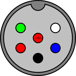
Monitor - RGB/CGA/EGA/YUV to VGA Arcade HD-Converter PCB (GBS-8220)
I've got one of these convertor boards so I can use VGA computer monitors with the arcade machine.
This is small enough to put it in the same enclosure as the PSU.
This is the one VGA output pictured below, they also make a dual VGA output version for running two monitors from one input.
Product Information
This CGA/EGA/YUV to VGA Arcade Converter PCB allows all types of RGB, EGA, VGA or YUV component signals to be up-converter and display on a 31KHz PC VGA monitor, TFT monitor, LCD display, or HD-TV with VGA connection. No dip switch settings, input frequency for all inputs are detected automatically.
An excellent alternative to an expensive, old, heavy CGA monitor. Use this converter with an existing computer monitor or use a light-weight LCD display.
Features/Specifications:
- Supports CGA/EGA/VGA/YUV Component Signal Input
- Supports VGA Output (640 x 480, 800 x 600, 1024 x 768, 1360 x 768)
- CGA/EGA/VGA signal auto scan (15KHz, 24KHz, 31KHz)
- YUV Component signal auto scan (480i, 576i, 720i, 1080i, 480p, 576p, 720p, 1080p)
- On Screen Display (English and Chinese)
- Supports image position control & image zoom control
- True digital 24-bit A/D converter for true 16.7-million colour conversion.
- Supports ALL types of VGA monitors (CRT, LCD, PDP, Projector, etc)
| Input Power | DC5V 2A +/- 0.5v | P7 or P9 | ||
|---|---|---|---|---|
| Input Signal | CGA/EGA | 14.5kHz - 16.5kHz 23.5kHz - 25.5kHz 30.5kHz - 32.5kHz |
Auto Scan | P3 or P11 or P10 |
| RGBHV | 30.5kHz - 32.5kHz | Auto Scan | P10 or P11 | |
| VGA | 30.5kHz - 32.5kHz | Auto Scan | P10 or P11 | |
| Ypbpr | 480p,576p,720p,1080p | Auto Scan | P2 | |
| Ycbcr | 480i,576i,720i,1080i | Auto Scan | P2 | |
| Output Signal | VGA | 640x480, 800x600, 1024x768, 1360x768 | P4 and P13 | |
| User Controls | Input Switch, Image Zoom, Image Position, Output Resolution, R\G\B gain adjust. |
Menu Key R\G\B VR |
||
| Dimensions | 115mm x 105mm x 20mm | |||
External Finished Pinouts on the Super Gun
NOTE: All views are the outside ports on the Super Gun.
This information will be useful for making cables.
Monitor
| Function | Colour |
|---|---|
| Video Ground | Black |
| Video RED | Red |
| Video GREEN | Green |
| Video BLUE | Blue |
| Video SYNC | White |
| +5 VDC | Red |
Joystick - D-sub
08 07 06 05 04 03 02 01
15 14 13 12 11 10 09
Player 1
Left hand connector
| Pin # | Function | Multi-Core Cable | Internal Colour |
|---|---|---|---|
| 01 | Ground | Black | Black |
| 02 | Player 2 Start | Pink | Green |
| 03 | Test Switch | Yellow/Red | Gray |
| 04 | Coin Switch 1 | Light Green | Orange |
| 05 | Player 1 Button 3 | Blue | White |
| 06 | Player 1 Button 2 | Green | White |
| 07 | Player 1 Button 1 | Red | White |
| 08 | Ground | Gray | Black |
| 09 | +5 VDC | Green/Red | Red |
| 10 | Player 1 - Right | White | Yellow |
| 11 | Player 1 - Left | Purple | Yellow |
| 12 | Player 1 - Down | Yellow | Yellow |
| 13 | Player 1 - Up | Brown | Yellow |
| 14 | Player 1 Start | Orange | White |
| 15 | +5 VDC | Blue/Red | Red |
Player 2
Right hand connector
| Pin # | Function | Multi-Core Cable | Internal Colour |
|---|---|---|---|
| 01 | Ground | Black | Black |
| 02 | Player 1 Start | Pink | White |
| 03 | Test Switch | Yellow/Red | Gray |
| 04 | Coin Switch 2 | Light Green | Orange |
| 05 | Player 2 Button 1 | Blue | Green |
| 06 | Player 2 Button 2 | Green | Green |
| 07 | Player 2 Button 3 | Red | Green |
| 08 | Ground | Gray | Black |
| 09 | +5 VDC | Green/Red | Red |
| 10 | Player 2 - 1 | White | Blue |
| 11 | Player 2 - 2 | Purple | Blue |
| 12 | Player 2 - 3 | Yellow | Blue |
| 13 | Player 2 - 4 | Brown | Blue |
| 14 | Player 2 Start | Orange | Green |
| 15 | +5 VDC | Blue/Red | Red |
JAMMA - D-sub
19 18 17 16 15 14 13 12 11 10 09 08 07 06 05 04 03 02 01
37 36 35 34 33 32 31 30 29 28 27 26 25 24 23 22 21 20
| Pin # | Function | Colour | - | Pin # | Function | Colour |
|---|---|---|---|---|---|---|
| 01 | Coin Switch 2 | Pink | - | 20 | Player 2 Button 1 (Red) | Green |
| 02 | Player 2 Start | Green | - | 21 | Player 2 Button 2 (Green) | Green |
| 03 | Player 2 - Up | Blue | - | 22 | Player 2 Button 3 (Blue) | Green |
| 04 | Player 2 - Down | Blue | - | 23 | +5 VDC | Red |
| 05 | Player 2 - Left | Blue | - | 24 | +12 VDC | Orange |
| 06 | Player 2 - Right | Blue | - | 25 | Speaker Negative (-) | White |
| 07 | -5 VDC | Purple | - | 26 | Video GREEN | Green |
| 08 | Ground | Black | - | 27 | Video SYNC | White |
| 09 | Ground | Black | - | 28 | Ground | Black |
| 10 | Coin Switch 1 | Orange | - | 29 | Ground | Black |
| 11 | Ground | Black | - | 30 | Video BLUE | Blue |
| 12 | Ground | Black | - | 31 | Video RED | Red |
| 13 | -5 VDC | Purple | - | 32 | Speaker Positive (+) | White |
| 14 | Player 1 - Right | Yellow | - | 33 | +12 VDC | Orange |
| 15 | Player 1 - Left | Yellow | - | 34 | +5 VDC | Red |
| 16 | Player 1 - Down | Yellow | - | 35 | Player 1 Button 3 (Blue) | White |
| 17 | Player 1 - Up | Yellow | - | 36 | Player 1 Button 2 (Green) | White |
| 18 | Player 1 Start | White | - | 37 | Player 1 Button 1 (Red) | White |
| 19 | Test Switch | Gray | -- |
[T O P]