Dual Headlight Loom Wire & Connectors.
![]()
The Replacement Wire:Before starting the dual headlight modification a replacement wire for the loom needs to be made to go in place of the one that has been removed by the manufacturer. There have been numerous different write ups on how to make this replacement wire, this is a sort of compilation using ideas from some of them and some ideas of my own showing what I have done.There seems to be some difficulty getting the correct 8.1mm spade connector for the block connector at the bulb end of the wire in this country, (UK) so a standard straight shank spade connector is modified to allow a 90° approach. The terminal for the block connector is manufactured out of some 0.65 thick brass, (see diagram at the foot of the page). The loom wire is 32 strand by 0.2mm wire 1.22 Meters long with an ampere rating of just over 8 amps, (minimum required must be at least 4.6 amps for a 55 Watt bulb), (55 Watts divided by 12 volts equals 4.6 amps). The Components:You will need these following items to make the replacement loom along with some other basic tools such as a soldering iron, a pair of wire cutters, wire strippers and a pair of pliers.
The Method:First, tin the two end connectors with leaded solder, this will make soldering the wire on easier at a later date, (Figures 1 & 2).Cut the wire to a length of 1.22 Meters Bare, twist and tin the end of the wire for 12mm then solder the wire to the terminal block connector, (figure 3). When the solder has cooled crimp the tabs around the wire with pliers. Cut two pieces of the yellow heat shrink tube to a length of approximately 50mm, slide these over a 1.17 meter length of the smaller sized 5mm diameter bore Flexo outer sleeving, pass the wire through the sleeving then apply heat to the heat shrink tube at the end you have just soldered the terminal to, this neatens the end and stops the Flexo sleeving from fraying. Bare, twist and tin the other end of the wire for 12mm then solder the wire to the spade connector ensuring the 90° approach is from the correct side, (figure 4) as it will only fit in to the bulb connector block one way round. Stretch the flexo cable to within 25mm of the other end and slide down the other piece of heat shrink tube until it meets the terminal joint. Apply heat to shrink the heat shrink tube, this neatens the other end and stops the Flexo sleeving from fraying. Cut two pieces of the black heat shrink tube to a length of approximately 60mm, slide these over a 1.17 meter length of the larger sized 8mm diameter bore Flexo outer sleeving, (you will need to experiment with the amount of stretch before cutting to length). Pass the newly created wire loom, (small terminal end first) through the larger bore Flexo Sleeving. Slide the two larger pieces of heat shrink tubing to each end and apply heat. This neatens the ends, stops the Flexo sleeving from fraying and adds a double thickness protection to the loom wire. The loom wire is now complete and ready for fitting to the bike, (figure 5). |
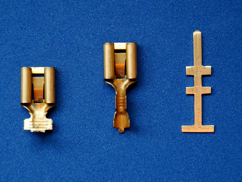 Wire Loom End Terminals.
 |
 Shrink Tube & Leaded Solder.
 |
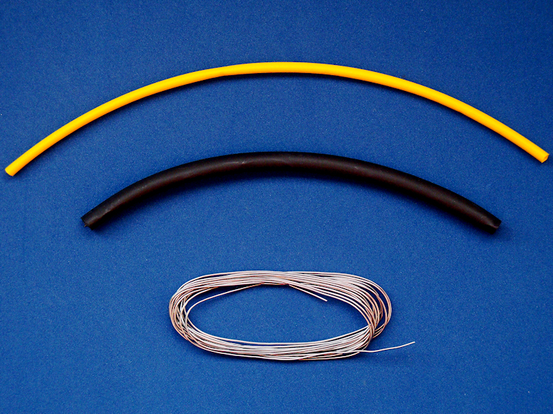
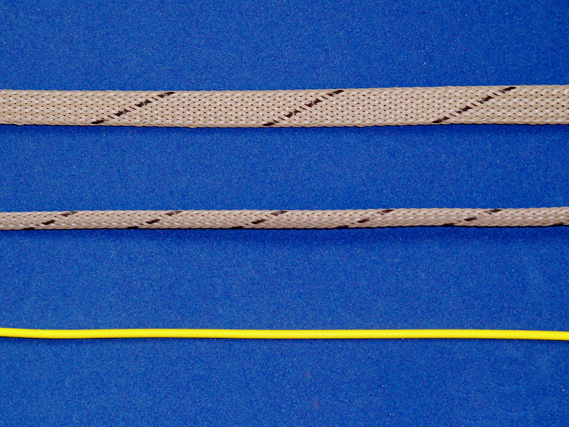 Outer Loom Sleeving & Wire.
 |
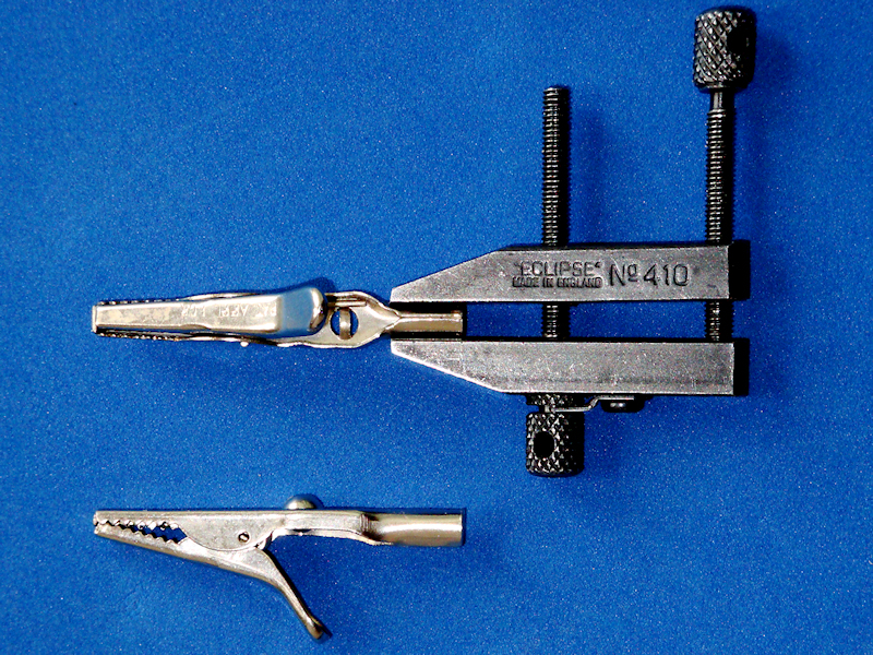 Improvised "Third Hand".
 |
|
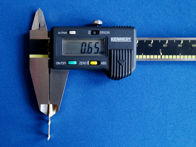 Check Brass Terminal Thickness.
 (0.65mm). |
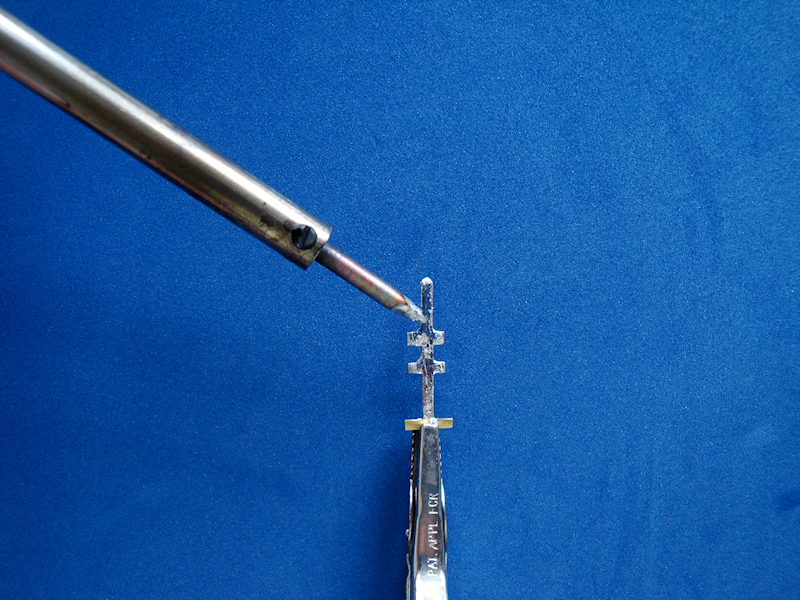 Tin The Connector With Solder.
Figure 1. |
|
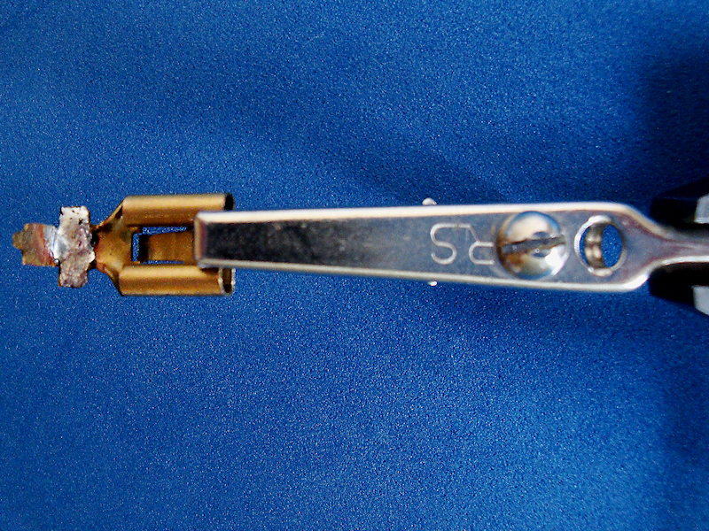 Tin The Connector With Solder.
 Figure 2. |
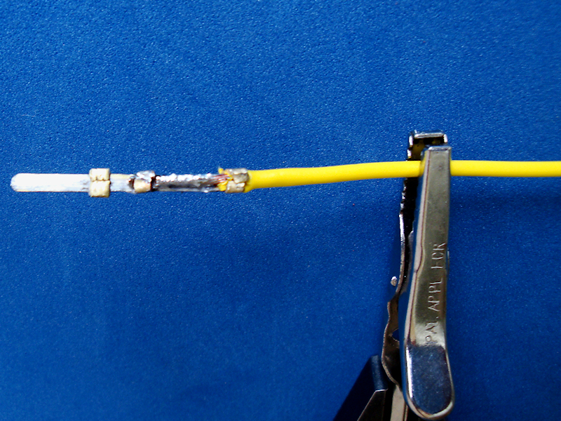 Solder and Crimp On The Wire.
Figure 3. |
|
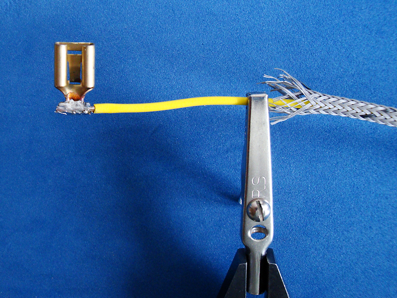 Solder and Crimp On The Wire.
 Figure 4. |
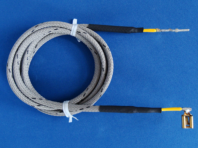 The Finished Loom Wire.
Figure 5. |
Terminal Pin Diagram: |