Navman S100 Satnav Mount Plate.
![]()
The Idea:To modify the homemade Universal Handlebar Platform Mount that I made at an earlier stage of a different project to house other homemade components so as to be able to mount my Navman "Spirit" S100 Satellite Navigation System at a reasonable viewing angle, something around 20° extra to the handlebar mount which already sits at about 20° giving a total angle of 40°.The Wedge Components:The first task was to manufacture the 20° angled wedge components out of Aluminium plate that happened to be 9mm thick. The width of the component was made to be 48mm, (slightly less than the platform mount width) and the highest point measured 34mm at the start of the 20° angle. Working from the centre of each face in turn I put two M5 x 0.8mm tapped holes on each angled face, 34mm apart to a depth of 8mm of thread then turning over to the other face I drilled two 3.3mm diameter dowel holes 34mm apart for a depth of 8mm. In the centre I drilled and tapped an M5 x 0.8mm hole to a thread depth of 16mm. These holes are then used to fix the wedge components to the platform mount, (see Figures 1 to 4).The Platform Mount Modification:To fit the wedge components to the platform mount new holes had to be drilled and counterbored into it to accommodate the fittings, as usual I worked from the centre of the plate. The first job though was to try and loose some weight from it as the thing was getting a bit heavy!
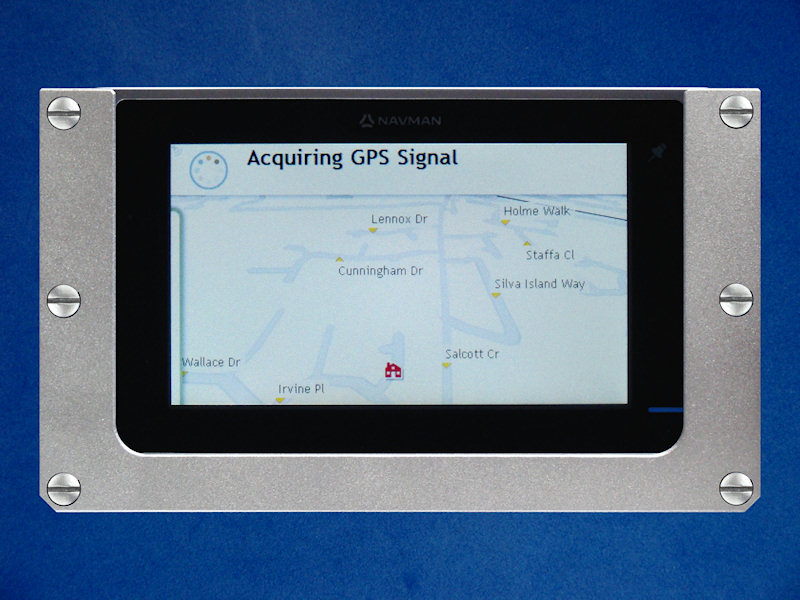
The Adapter plate:As this is unique to the satnav device I have chosen to use, (a Navman "Spirit" S100 Satellite Navigation System) I am not going to go into too much detail with dimensions at this stage as they would only be relevant to the S100 and therefore pointless if a different satnav system is to be used. The idea however should be similar.
The Cover Plate:This is literally to stop the satnav unit falling out of the adapter plate. It is a piece of 2mm thick Aluminium that is to the same external dimensions as the adapter plate, (150mm x 78mm) but the internal size is smaller in width than the adapter plate internal pocket by 12mm giving an overlap each side of 6mm. It is held in place by six M4 x 0.7 x 8mm cheese head screws that each have a spring washer underneath to allow movement in the cover plate, (see Figures 7 to 9).The Assembly:First fit the two 20° wedges to the platform mount. This is done by locating the wedges using the four split dowels, (two for each wedge) and bolting the wedge down from underneath using the two M5 cap head bolts. Using the four M5 countersink screws the adapter plate is fitted to the angled face of the wedges. The cover plate is then fitted using the six M4 cheese head screws with spring washers underneath, (tighten these screws until a slight resistance is felt, do not over tighten) this allows the cover plate to move within the tension of the spring washers. It may be a good idea to use a retaining compound on the threads of the screws to stop them undoing due to vibration. See Figures 10 to 12 for the fitting components and finished article. |
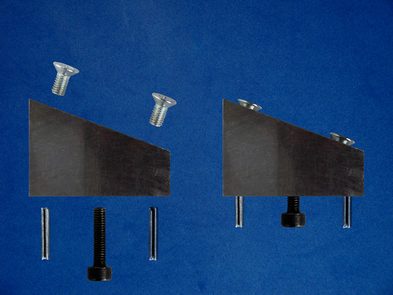 20° Angle Wedge Components.
Figure 1. |
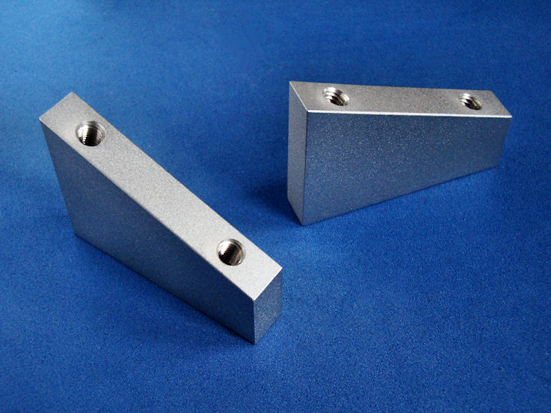 20° Angled Adapter Wedges.
Figure 2. |
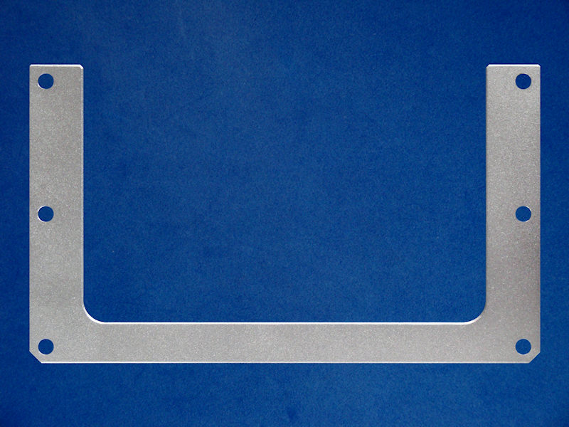
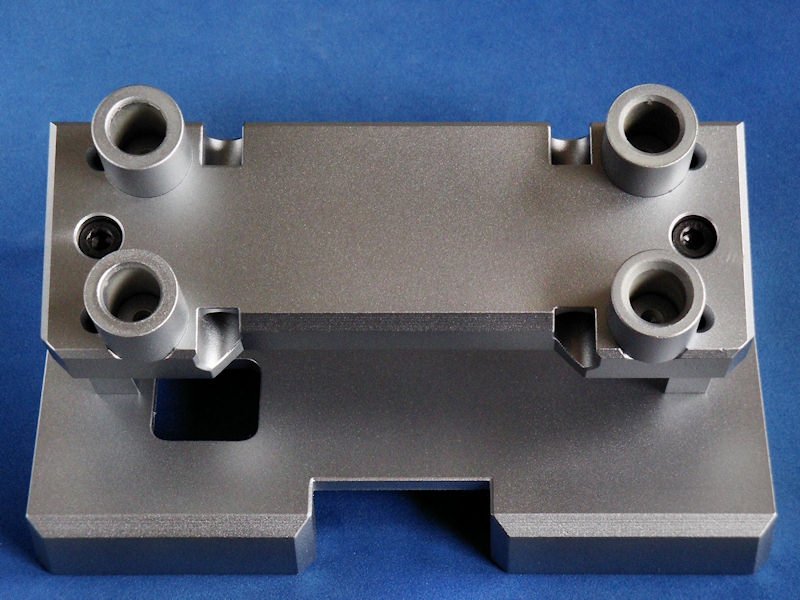
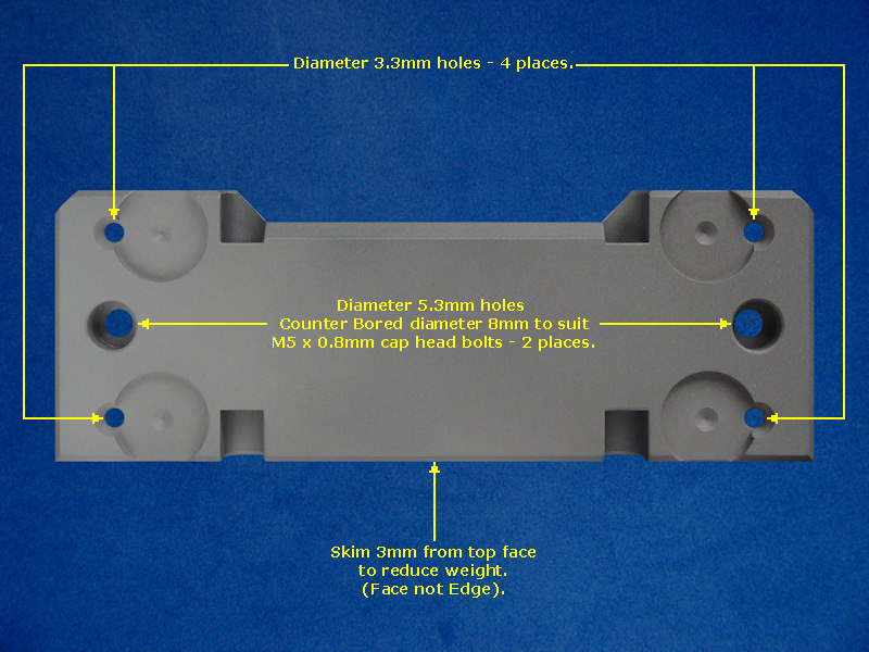 Modified Platform Mount.
Figure 3. |
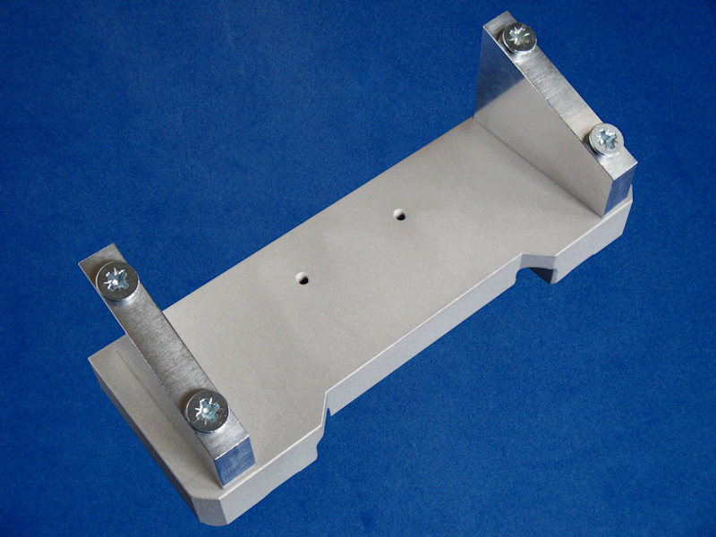 Modified Mount & Wedges..
Figure 4. |
|
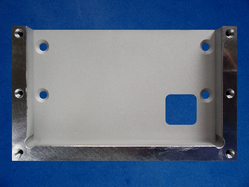 Adapter Plate.
Figure 5. |
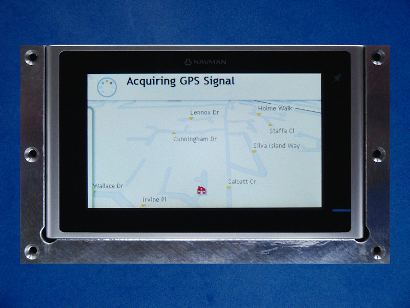 Adapter Plate & S100 Unit
Figure 6. |
|
 Cover Plate
Figure 7. |
 Cover Plate & Adapter Plate.
Figure 8. |
|
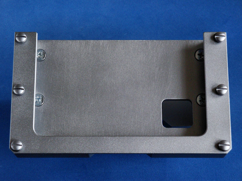
 Cover Plate & Navman S100 Unit.
Figure 9. |
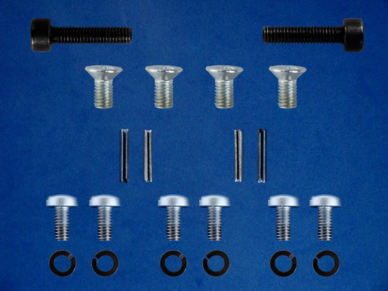 Component Fixings.
Figure 10. |
|
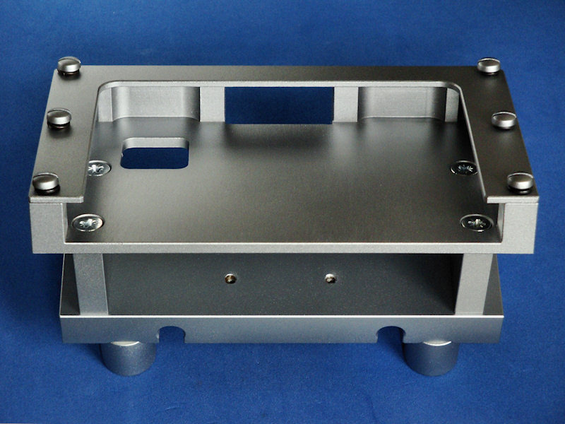
 Underside Assembly View.
Figure 11. |
 Face On Assembly View.
Figure 12. |
|
So Did It Work? (13/05/11):Well yes and no. The bracket holds the satnav unit in place like it is supposed to and the positioning is pretty good for angle and viewpoint. Unfortunately the screen is hard to see with a crash helmet visor and sunglasses, (which is what I wore today whilst testing it) so I had to rely on audio directions which was very clear. This was achieved using "in ear" headphones, (which were quite comfortable surprisingly) and I did reach my programmed destination without a hitch. I have since found some more settings and increased the brightness of the screen from 70% to 100% so I will see how it fares next time. The other downside is that I got a low battery warning after about 45 minutes of use. The power in slot is the same as the audio out slot, (uses an adapter block for a 3.5mm audio jack plug) so I can't use power from the bike. It would be OK to get you out of trouble if you got lost but a journey of more than 45 minutes and it would struggle. |
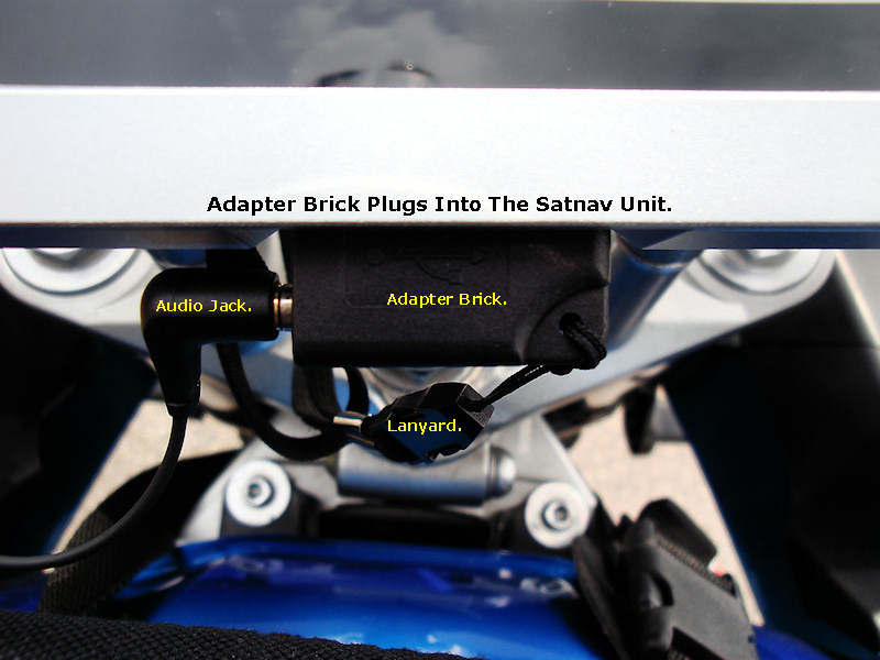 Audio Adapter Brick.
Figure 13. |
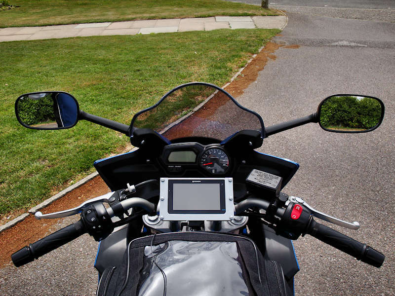 Placement On The Bike.
Figure 14. |