MD80 Mini DV Camera Mount Bracket Mark IV.
![]()
Evolution II:After yet another rethink it was decided that another modification to the bracket was required this time to make it a bit more universal for general use on and off of the bike. Once again a derivative of the Mark II bracket) but this time it is of a more stocky design with a 1/4" UNC x 20 thread on either side of the bracket body and one in the base. This can then be used free standing or with one of the homemade bracket arms. Like before the standard camera mount fixing will house to other camera holding devices such as a tripod or ram mount.The Bracket Body:My design for the bracket components are somewhat over engineered simply because I have access to the machinery and materials to be able to do the job. The main important dimension is for the slot that the camera sits in, the rest is open to adjustment.
The Camera Clamp:This is the component that is going to hold the camera in place on the bracket in the machined slot, it is identical to the one found on the Mark II bracket only this time I have painted it black.
The Footage:Using the picture link, (figure 8) you can visit You Tube and see some of the video footage captured from this camera. Bear in mind the original video quality has been compressed for uploading and as a result is not as good. |
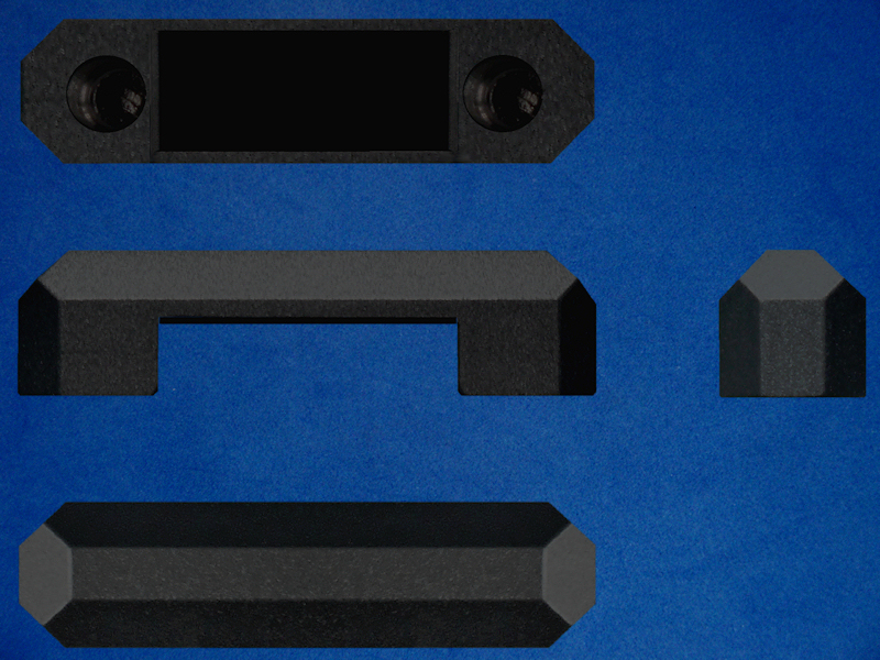
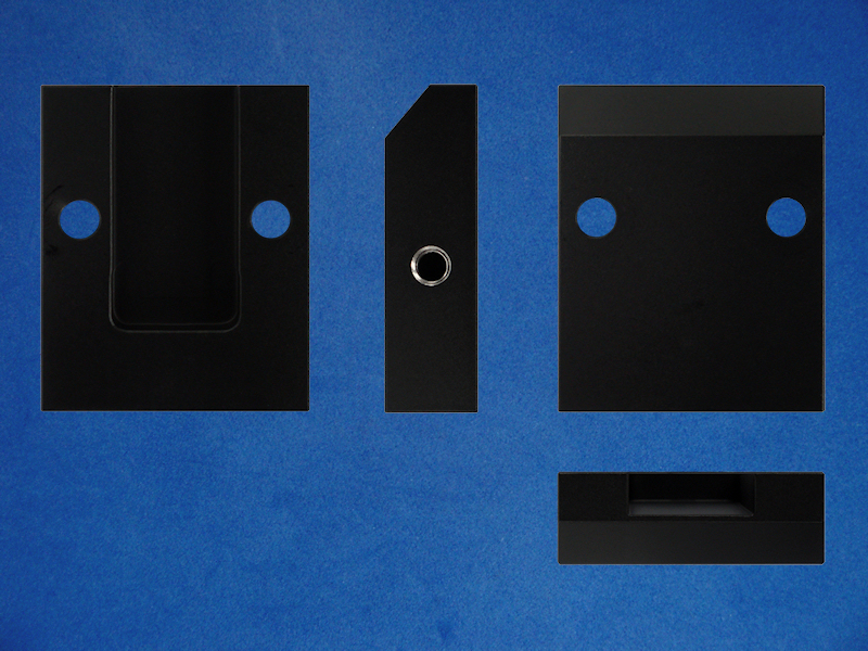 Mark IV Bracket All Views.
Figure 1. |
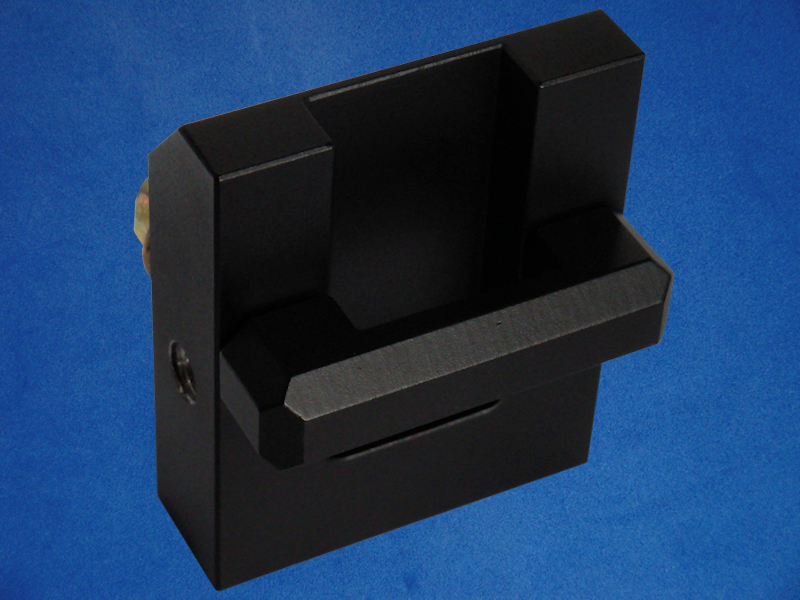 Isometric Image.
Figure 2. |
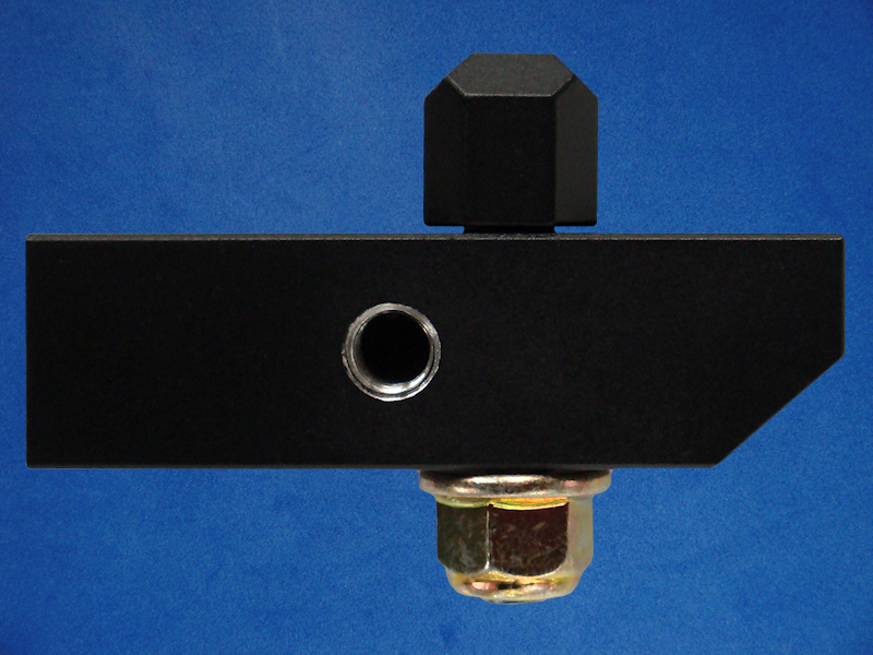
 Left Hand View.
Figure 3. |
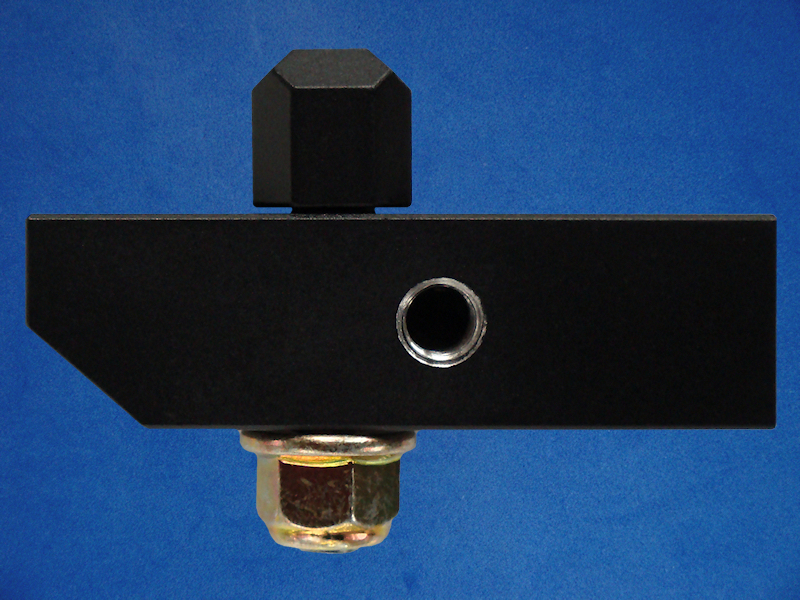
 Bracket Top View.
Figure 4. |
|
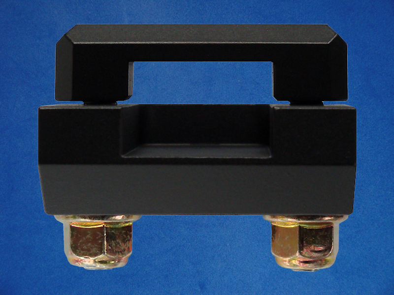
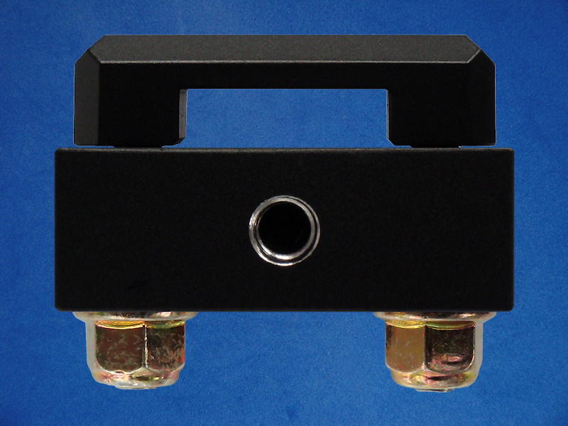
 Right Hand View.
Figure 5. |
 Bracket Base View.
Figure 6. |
|
 Camera Clamp All Views.
Figure 7. |
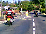 You Tube Video Link. You Tube Video Link.Figure 8. |
Diagram 1: Mark IV Bracket Body (Basic Block Shape). |
Diagram 2: Camera Clamp (Basic Block Shape). |