MD80 Mini DV Camera Mount Bracket Mark II.
![]()
The Next Idea:Having found a small video camera that worked on my bike to an acceptable level, (the MD80 Mini DV camera) it was now a case of finding somewhere more suitable to mount the thing but in a place where it would not be influenced to much by vibration and the operation of the bike. So far my experimental "Mark 1" bracket proved that video capture was possible but the quality had been influenced by the steering motion of the bike and the issue of trying to focus through a "double bubble" screen resulting in somewhat wobbly footage.The New Placement:Having tried mounting on the handlebar clamp and then focusing through the screen I opted to try and move the camera forward and mount it rigidly in a fixed point behind the screen rather than having it move with the steering. This required making some sort of fixing bar to bridge across behind the screen hopefully using existing screws to fix it in place.The Crossbar:I found an old piece of chrome plated 10mm diameter tube, (figure 1) in my shed, (forget where it was originally from). flattened and bent the ends to roughly the angle required for the fixing point on to the bike, (Figure 2). then drilled and filed two 5mm slots about 8mm long, (figure 3). This was to allow for any discrepancy in measurement. Offering it up to the bike for inspection I was satisfied that the slots and angle of bend were good enough and fixed it to the bike using existing screws, (figures 4, 5 & 6).The Pivot Bracket:My design for the bracket and clamp are somewhat over engineered simply because I have access to the machinery and materials to be able to do the job. The main important dimension is for the slot that the camera sits in, the rest is open to adjustment.
The Pivot Bracket Clamp:This is the component that is going to be used to clamp the pivot bracket to the crossbar. Once again the one I have made is a bit over engineered for what it does and can be made much simpler for function.
The Camera Clamp:This is the component that is going to hold the camera in place on the bracket in the machined slot. The placement of the clamp will also help to retain the Micro SD card should it work loose under vibration.
The Footage:Using the picture link, (figure 14) you can visit You Tube and see some of the video footage captured from this camera. Bear in mind the original video quality has been compressed for uploading and as a result is not as good. |
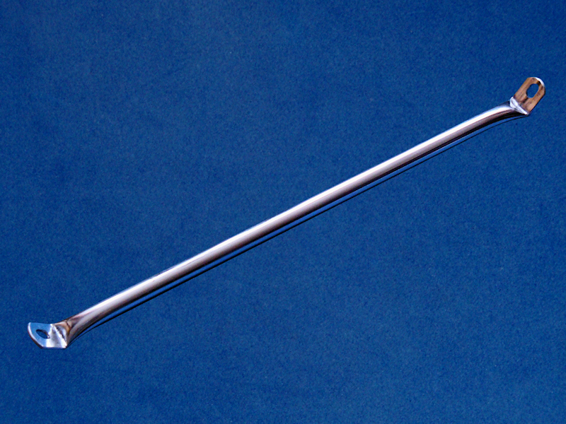 Chrome Tube.
Figure 1. |
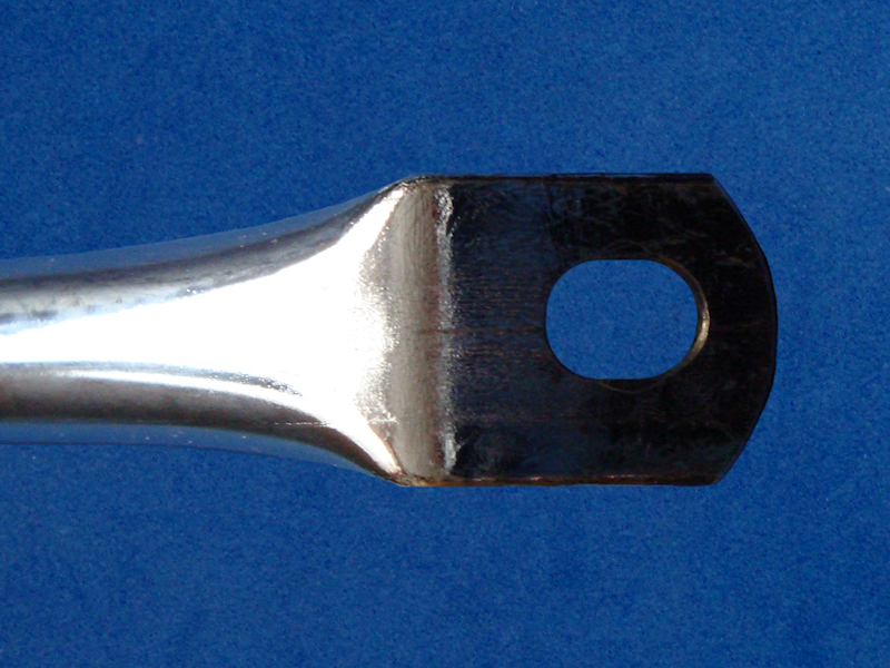
 Fattened & Bent End.
Figure 2. |
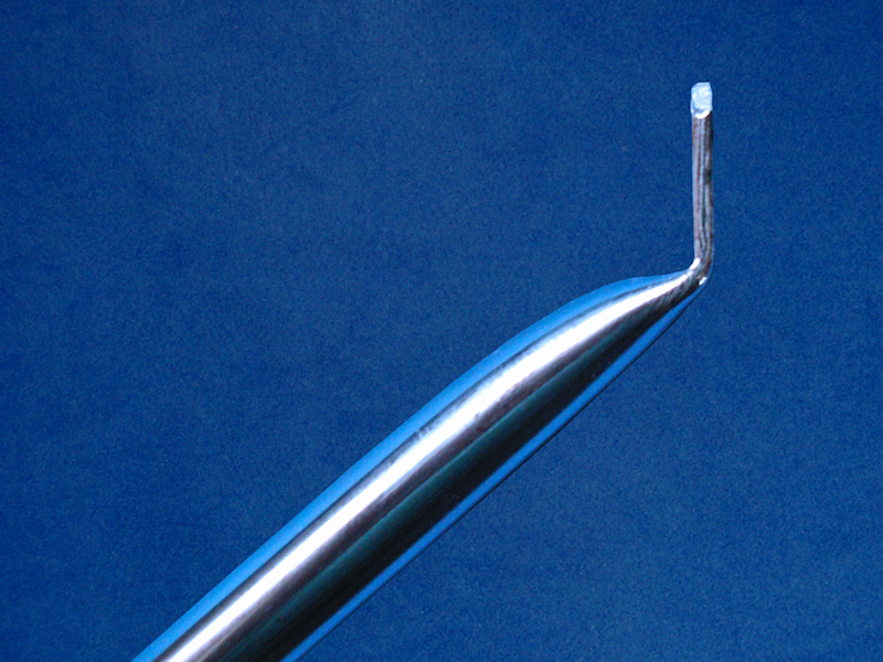
 5mm by 8mm Slot.
Figure 3. |
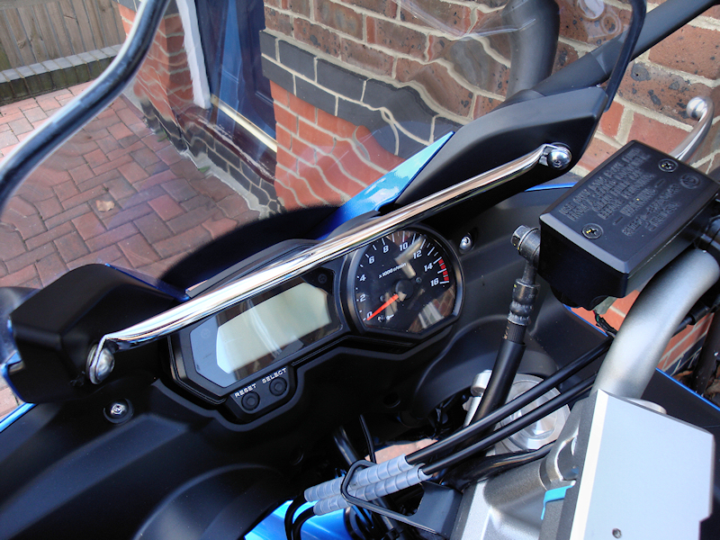
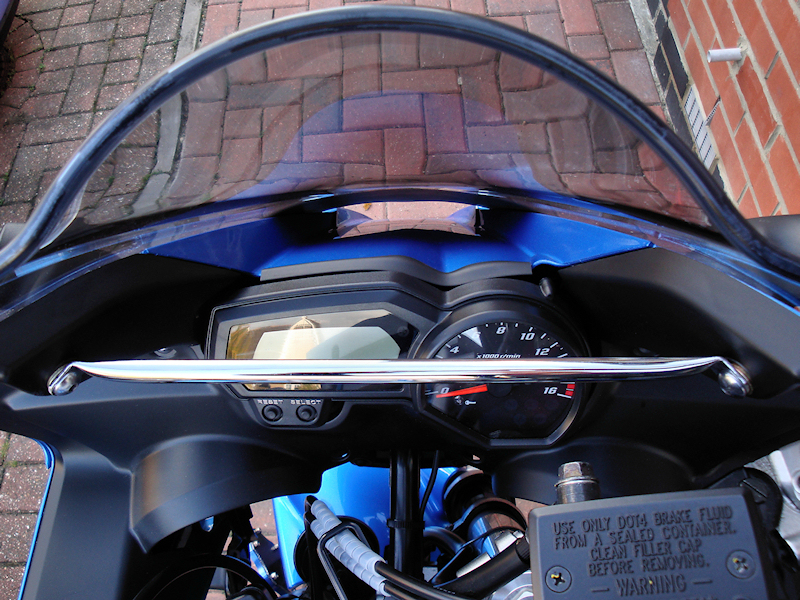 Crossbar Fixing Points On Bike.
Figure 4. |
|
 Crossbar Fixing Points On Bike.
Figure 5. |
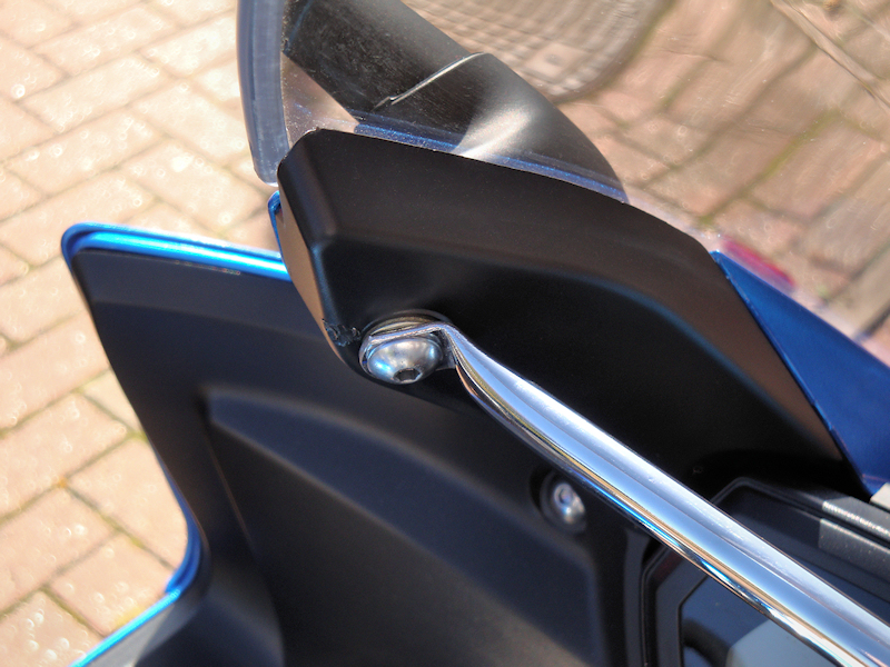 Crossbar Fixing Point.
Figure 6. |
|
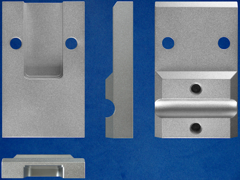 Pivot Bracket All Views.
Figure 7. |
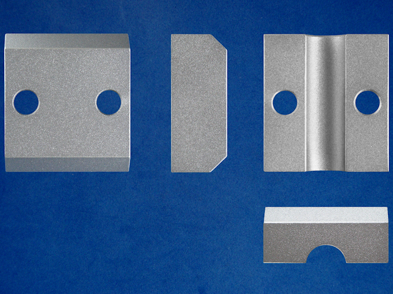 Bracket Clamp All Views.
Figure 8. |
|
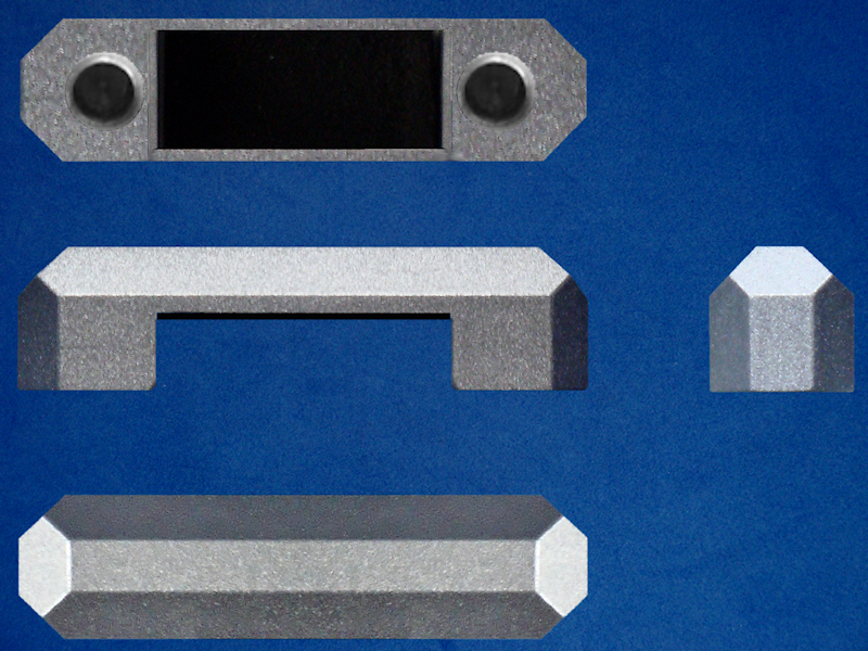 Camera Clamp All Views.
Figure 9. |
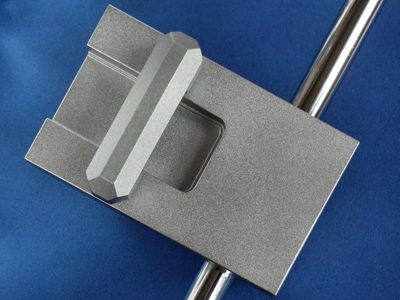 Painted Bracket Assembly.
Figure 10. |
|
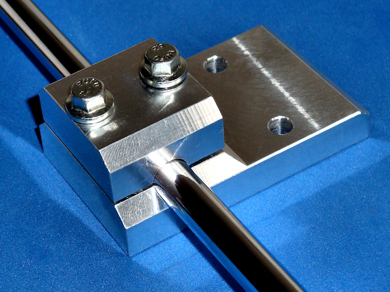 Pre Painted Bracket Assembly.
Figure 11. |
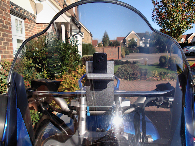
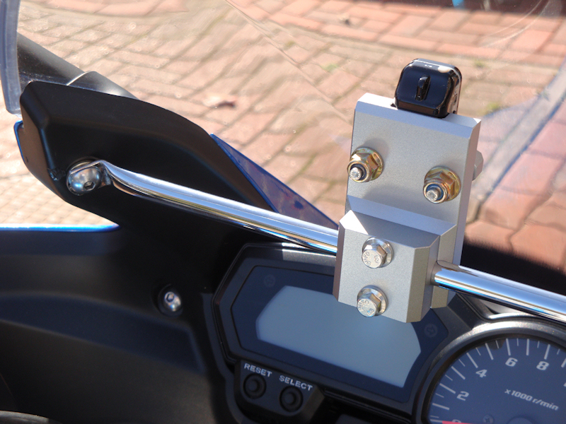 Mounted Bracket Assembly.
Figure 12. |
|
 Mounted Bracket Assembly.
Figure 13. |
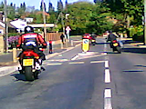 You Tube Video Link. You Tube Video Link.Figure 14. |
Diagram 1: Mark II Pivot Bracket (Basic Block Shape). |
Diagram 2: Pivot Bracket Clamp (Basic Block Shape). |
Diagram 3: Camera Clamp (Basic Block Shape). |