MD80 Mini DV Camera Mount Bracket Mark I.
![]()
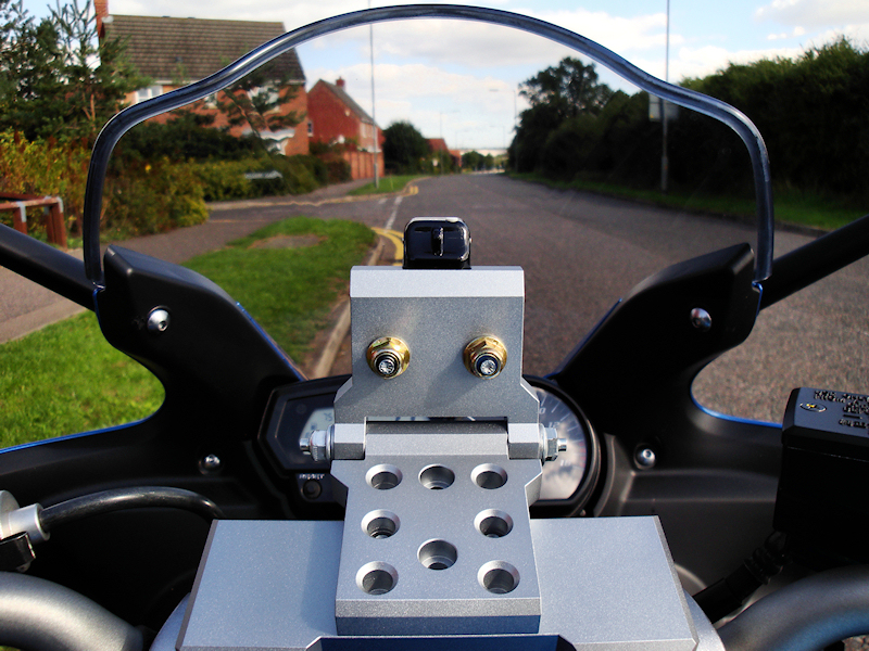
The Idea:I wanted to be able to mount a small video camera somewhere on the bike for the purpose of capturing video footage during local ride outs, this could then be edited and placed on You Tube for fun. I needed to find a place that would provide easy access to turn the camera on and off and such a place that would minimise vibration hence it would have to be mounted in a sturdy fashion.The Placement:I opted for placing a camera over the handlebar clamp using a secondary platform, the camera could then be attached to this and adjusted to suit pointing through the windshield. My way of thinking was this. As the platform was on the handlebar clamp which is in turn connected to the forks a natural damping effect should happen as it is the forks and suspension that smooth out the ride in the first place.The Video Camera:I purchased a MD80 Mini DV Camera for £9, this uses a Micro SD card of which I managed to get an 8 Gigabyte, Class six card for £11 so the project stands me at around £20 to start with. I made a secondary platform and attached it to the bike using cable ties, (easy to remove but sturdy when in position) I then attached the swivel bracket that came with the camera kit to this platform, (figures 1 & 2). Disappointingly the bracket that came with the camera in the kit was to flimsy and the video footage showed signs of vibration so I set about making a more "beefy" bracket to do the job.The Base Plate:This is the part that is going to marry up with the existing M3 x 0.5mm tapped holes that I put in the platform component that originally mounted the supplied plastic swivel bracket. I will also include a series of other holes to allow movement on the platform and the possibility of mounting it in a different location altogether. The following describes the method to produce a basic base plate, one with non-complicated shape unlike the one I produced...
The Swivel Plate:This component is going to house the MD80 Mini DV camera and attach to the base plate to create an adjustable bracket that can be set to different required angles. These can then be locked into position using lock nuts and studding. The following roughly describes the method to produce a basic swivel plate, one with non-complicated shape unlike the one I produced...
The Camera Clamp:This is the component that is going to hold the camera in place on the bracket in the machined slot. The placement of the clamp will also help to retain the Micro SD card should it work loose under vibration. The following describes the method to produce a basic camera clamp...
Fitting To The Bike:Having completed the new bracket this bit is the simple bit. Using a couple of M3 x 0.5mm screws with a thread of 8mm in length the base plate can be attached to the original platform that I made to house the supplied plastic bracket. The camera angle can then be adjusted and locked using the two nuts at the side of the swivel section. It is worth noting that the clamp holding the camera in place uses two nylock nuts that are only "nipped" up enough to hold the camera in place. Over tightening these nuts could damage the camera casing and the internal components.Use picture links, (figures 15 and 16) to link to video footage captured from this position posted onto You Tube. A Mark II version of this bracket has also been made to fit the camera in a slightly different location! |
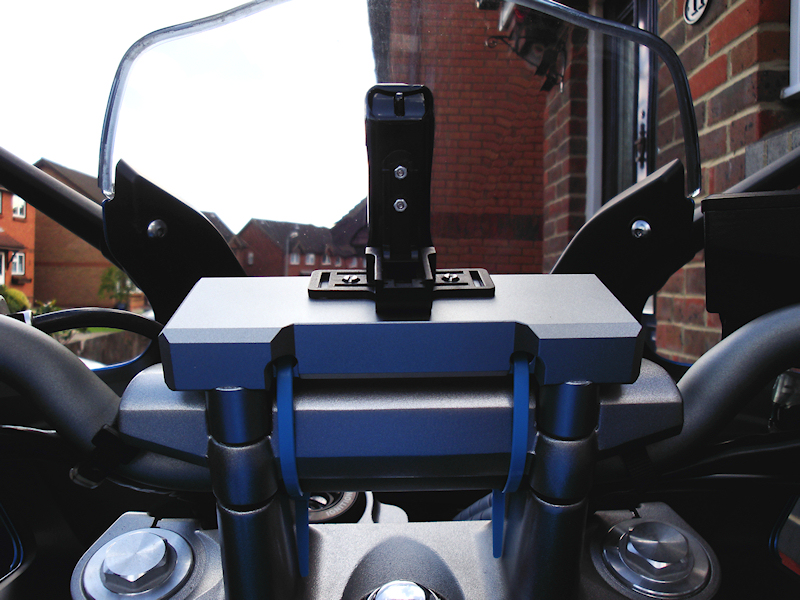 Platform & Camera Rear View..
Figure 1. |
 Fork Clamp Collar Top View.
Figure 2. |
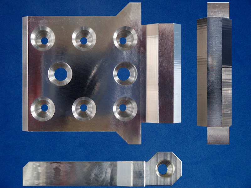 Base Plate (Three Views).
Figure 3. |
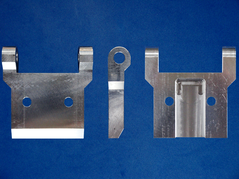 Swivel Plate (Three Views).
Figure 4. |
|
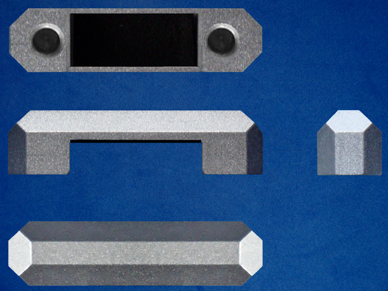 Camera Clamp All Views.
Figure 5. |
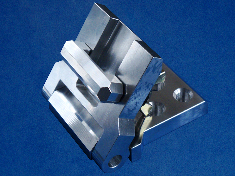 Front View Layout.
Figure 6. |
|
 Rear View Layout.
Figure 7. |
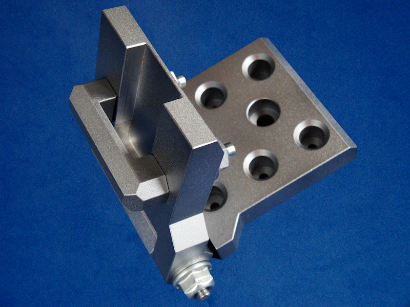 Painted Assembly Side View.
Figure 8. |
|
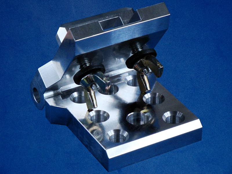
 Painted Assembly Underneath.
Figure 9. |
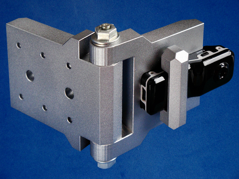
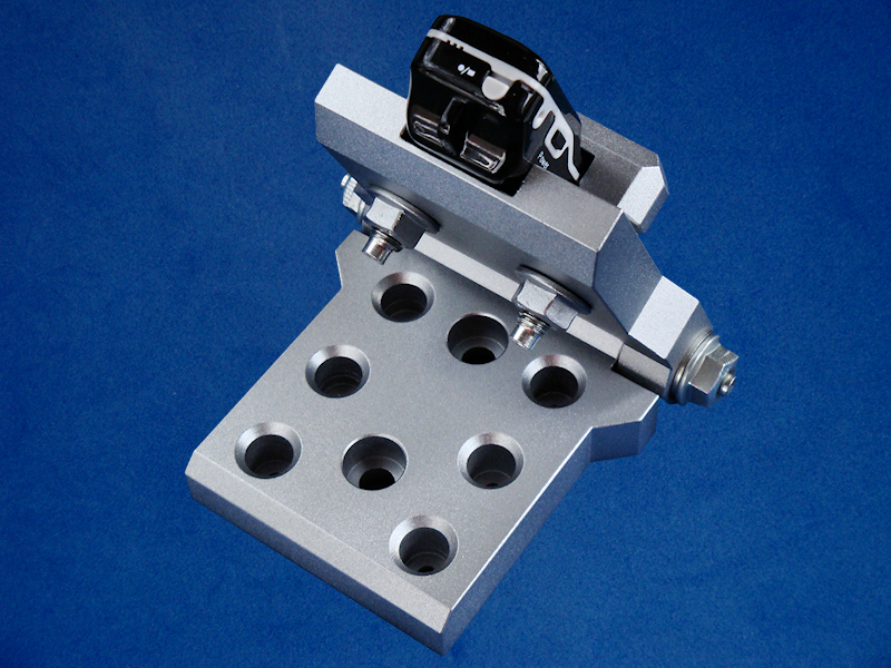 Camera Fitted Rear View.
Figure 10. |
|
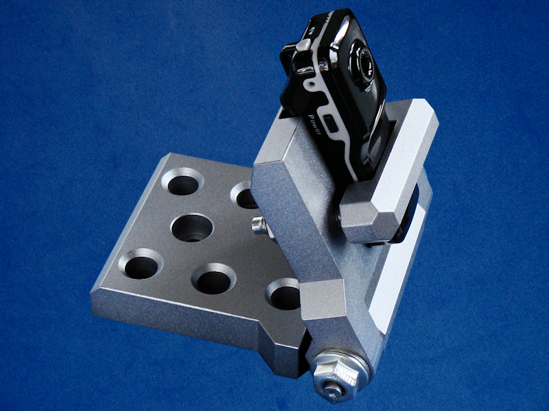 Camera Fitted Side View.
Figure 11. |
 On The Bike Front View.
Figure 12. |
|
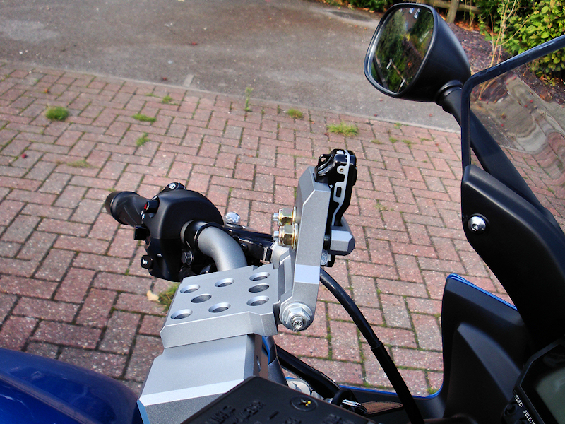 On The Bike Side View.
Figure 13. |
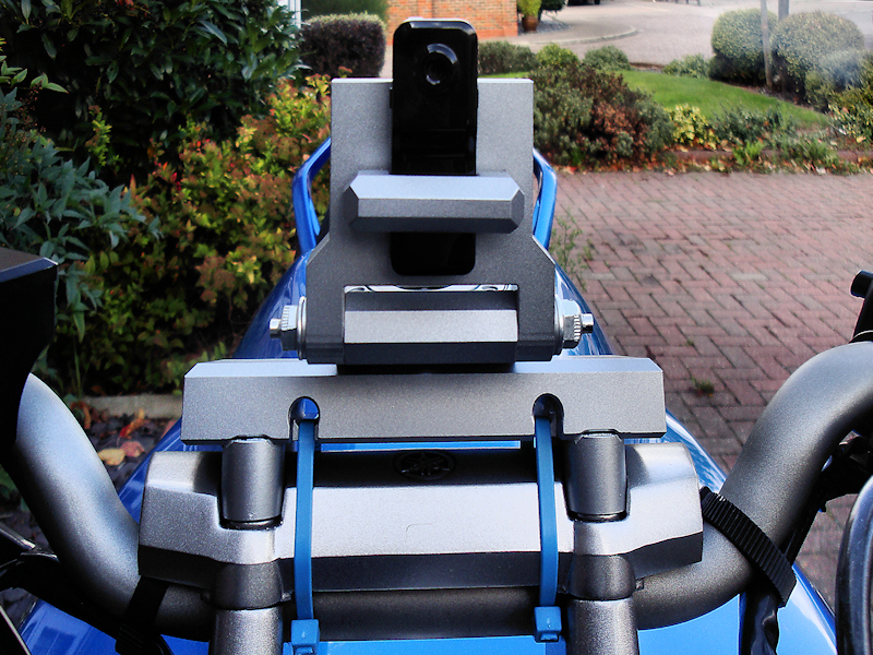
 On The Bike Rear View.
Figure 14. |
|
 You Tube Video Link. You Tube Video Link.Figure 15. |
 You Tube Video Link. You Tube Video Link.Figure 16. |
Diagram 1: Base Plate (Basic Block Shape). |
Diagram 2: Swivel Plate (Basic Block Shape). |
Diagram 3: Camera Clamp (Basic Block Shape). |