MD80 Mini DV Camera Mount Bracket Mark III.
![]()
Evolution:It is the nature of prototype designs that as you develop ideas new ones come to mind which means things need to be modified from the original idea. This bracket, (a derivative of the Mark II bracket) utilises a "Vee" clamp method instead of a dedicated diameter to clamp the bracket in different locations. This gives the chosen place to house the bracket more scope as the "Vee" can accommodate a different diameter range from 10mm up to 16mm without loosing clamping ability where as the Mark II bracket could only clamp to diameter 10mm fixing locations. I have also added a 1/4" UNC x 20 thread on either side of the bracket body for standard camera mount fixing for other camera holding devices available, (tripod, ram mount etc).The New Placement:The idea behind this design is to place the bracket and camera in multiple positions without to much bother. Utilising a "Vee" clamp system the bracket along with the camera can be placed anywhere where there is a handy diameter or post to clamp to, (rear racking system tubing for example) this way some rear facing footage can be obtained.The Pivot Bracket:My design for the bracket and clamp are somewhat over engineered like previous designs simply because I have access to the machinery and materials to be able to do the job. The main important dimension is for the slot that the camera sits in, the rest is open to adjustment.
The Pivot Bracket Clamp:This is the component that is going to be used to clamp the pivot bracket to different diameters. Once again the one I have made is a bit over engineered for what it does and can be made much simpler for function.
The Camera Clamp:This is the component that is going to hold the camera in place on the bracket in the machined slot, it is identical to the one found on the Mark II bracket only this time I have painted it black.
The Footage:Using the picture link, (figure 12) you can visit You Tube and see some of the video footage captured from this camera. Bear in mind the original video quality has been compressed for uploading and as a result is not as good. |
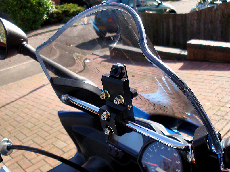 Front Mounted On Fazer.
Figure 1. |
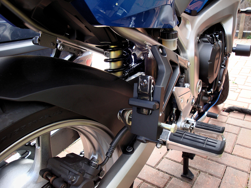 Makeshift Rear Mount.
Figure 2. |
 Rear Rack Mount.
Figure 3. |
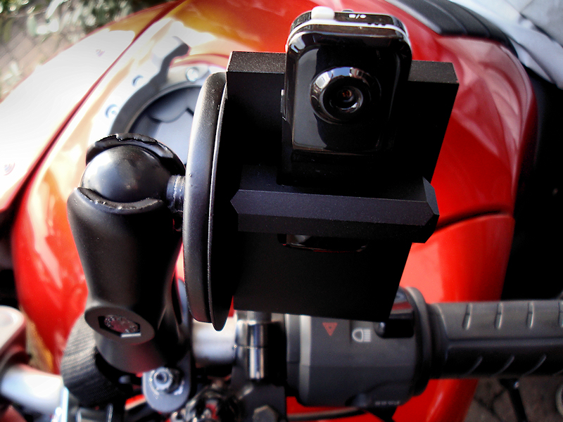 Ram Mount Fixing.
Figure 4. |
|
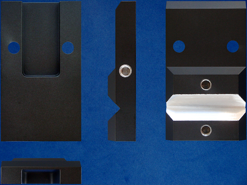 Pivot "Vee" Bracket All Views.
Figure 5. |
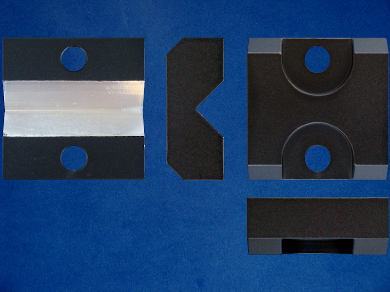 Bracket Clamp All Views.
Figure 6. |
|
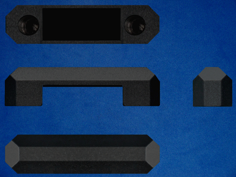 Camera Clamp All Views.
Figure 7. |
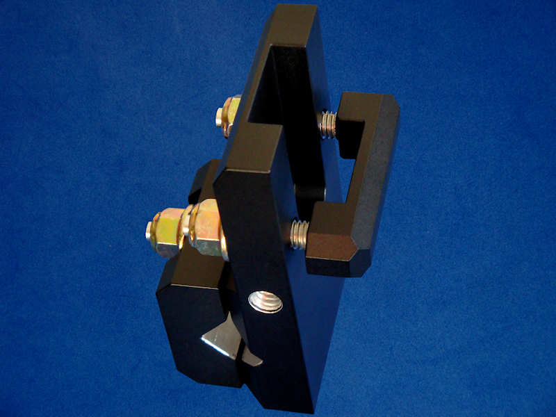 Painted Bracket Assembly.
Figure 8. |
|
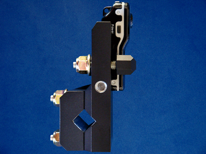 Camera & Bracket Side View.
Figure 9. |
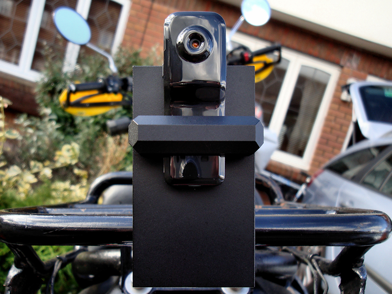
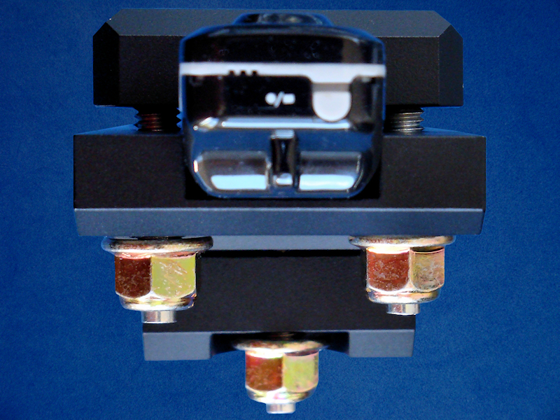
 Camera & Bracket Rear View.
Figure 10. |
|
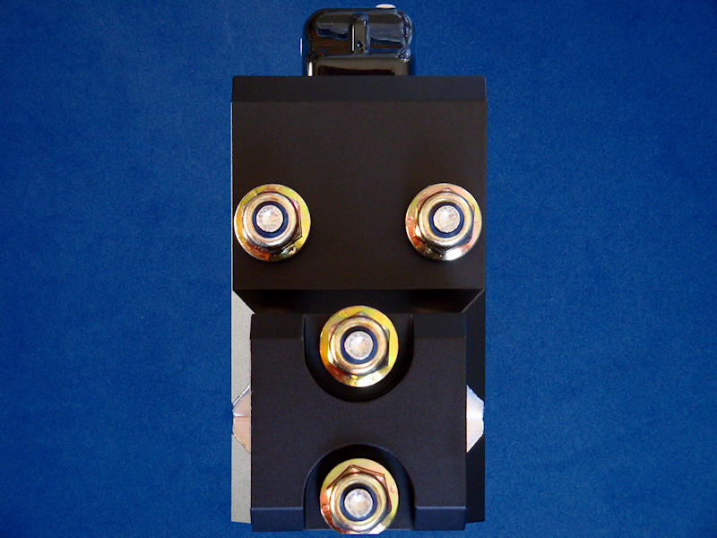
 Camera & Bracket Top View.
Figure 11. |
 You Tube Video Link. You Tube Video Link.Figure 12. |
Diagram 1: Mark III Pivot Bracket (Basic Block Shape). |
Diagram 2: Mark III Pivot Bracket Clamp (Basic Block Shape). |
Diagram 3: Camera Clamp (Basic Block Shape). |