Cable Layout:
I was originally intending to run the cable to a point under the seat of the bike but this proved impractical as there was no good fixing point for the block connector plus the lead was to short. I opted to go forwards through the frame following some existing cables with the thought that it must be reasonably safe as it was an existing electrical cable route.
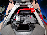
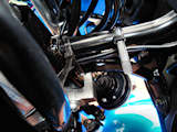
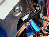
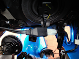
First I had to get to the battery which meant raising the petrol tank, (consult your user guide for this) I then disconnected the battery and positioned the leads in the position they were going to lie, (figure 1). I then threaded the lead with the block connector end on it through the frame taking the same route as an existing cable, (figure 2). Once I was happy with the layout I cable tied the permanent charger cable to the front stay, (figure 3) as this is a non moving part of the bike the cables are less likely to chafe or wear. The next test was to check that I could access the block connector without to much trouble, there is a handy slot in the fairing by the indicator mount to the right of the bike, (when sat on). This is ideal for passing the extension cable (TM-73) for the Optimate 4 battery charger through, (figure 4). Lastly I connected the cable terminals to the battery terminals ensuring the positive and negative connections were the correct way round.
A quick check that the charger worked when it was connected via the planned route and it was a case of putting the bike back together then once again checking everything worked OK not forgetting to re-set the clock on the bike instrument cluster. |

The layout of the new permanent charger cable shown here with the battery terminals disconnected ready for re-connection once the charger cable has been routed through the bike.
Battery Terminal
Point Layout.
Figure 1.

Cable ties are used to hold the permanent charger cable to the front Stay to keep it out of the way of the steering mechanism and other moving parts.
Cable Tie To Front Stay.
Figure 3.
|

The charger cable is passed through the bike frame taking a similar route to an existing cable which in theory should be a safe route to take.
Bike Frame
Cable Layout
Figure 2.

This picture shows the route the cable takes through the fairing slot to the battery charger by means of the optional 2.5 meter extension cable.
Connect To Optimate 4 Charger.
Figure 4.
|
![]()
![]()