Drift X170 Action Camera Fork Collar & Mount Bracket.
![]()
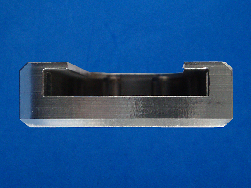
Please Note:This fork clamp collar and bracket is designed to fit a Kawasaki 650 Versys not the Yamaha FZ6 Fazer! However it is still a "homemade" item and I see no reason why a similar design with adjusted sizes could not be used on the Yamaha FZ6 Fazer if so desired.The Idea:There is a nice 52mm diameter machined section on the forks just below the bottom steering yoke that might make a suitable place for mounting the Drift X170 Action Camera. About 22mm in length it means the bracket or collar would not be to big and heavy and on initial inspection it will not interfere with the travel of the fork suspension movement. The plan is to construct a collar and arm to clamp to this machined area and project the Drift X170 Action Camera just below the headlight either on the right hand side or left hand side fork to give an alternative perspective when filming. The collar and arm is to be manufactured in such a way that there is some adjustment to the camera for fine tweaking of film angle.The Fork Clamp Collar:As there is 22mm of machined diameter spare on the bike forks it seems only logical to make the collar 22mm thick. The following is a rough guide to the manufacture of this fork clamp collar.
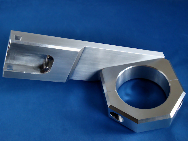
The Bracket Arm:As a rough estimate using a bit of trigonometry from some ruler measurements it was decided that the fork pitch angle was going to be around 24 degrees. Using this information a bracket arm was constructed to fit to the fork clamp collar. The following is a rough guide to manufacture of this bracket arm, (use the pictures opposite and the diagram below for reference).
Fitting To The Bike:All that remains now is to assemble the items and fit them to the bike. The camera alignment can be fine tuned by turning the collar on the fork leg so it is facing "true" forward or any desired angle. Other adjustments can be made to the Drift X170 Action Camera and mount as the lens is able to rotate and the supplied mount plate has notched grooves that allow incremental rotation and lock. Just for good measure a matching fork clamp collar was produced for the opposite fork so the bracket can be mounted to the left or to the right, the only difference being that the opposite fork has to have the camera mounted on the outside. |
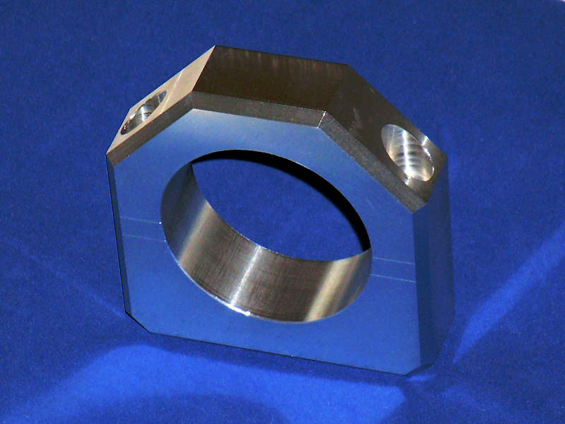 Fork Clamp Collar Front View.
Figure 1. |
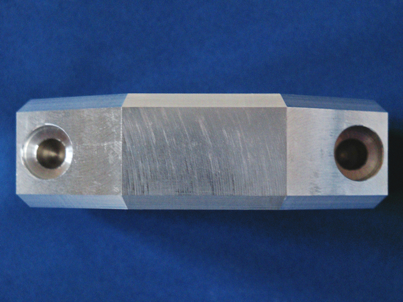 Fork Clamp Collar Top View.
Figure 2. |
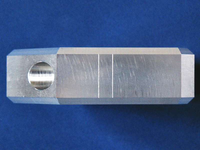 Fork Clamp Collar Side View.
Figure 3. |
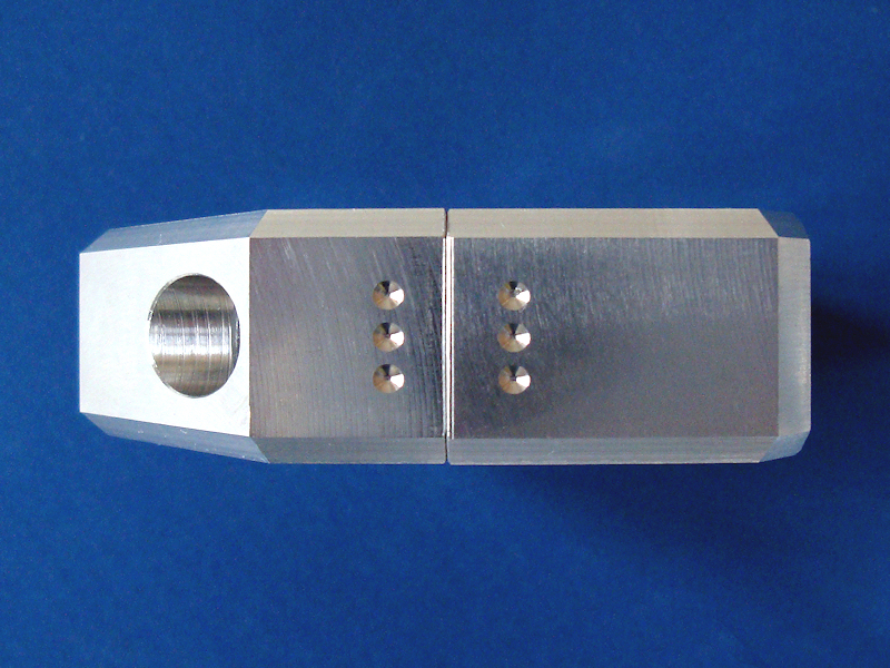 Fork Clamp Collar Side View.
Figure 4. |
|
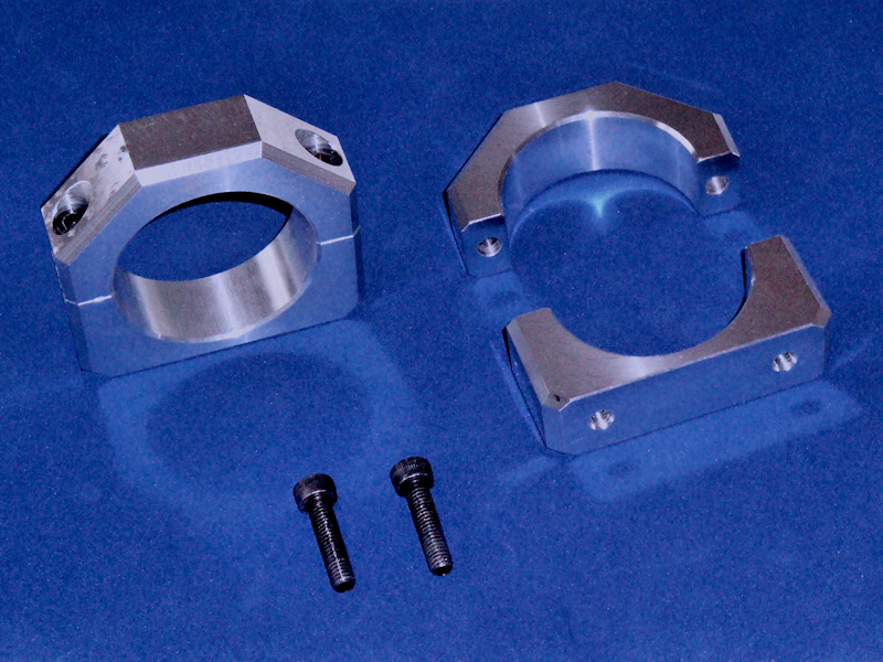 Fork Clamp Collar Components.
Figure 5. |
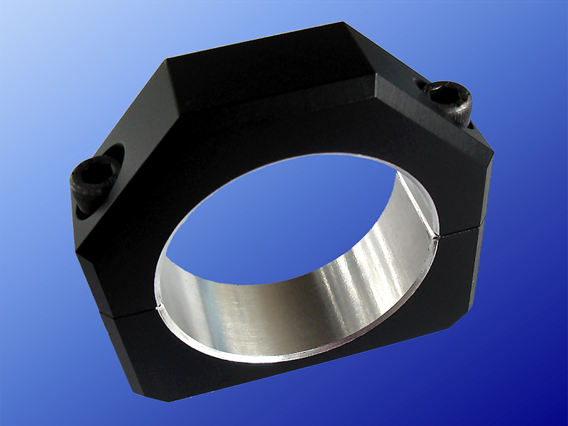 Fork Clamp Collar Complete.
Figure 6. |
|
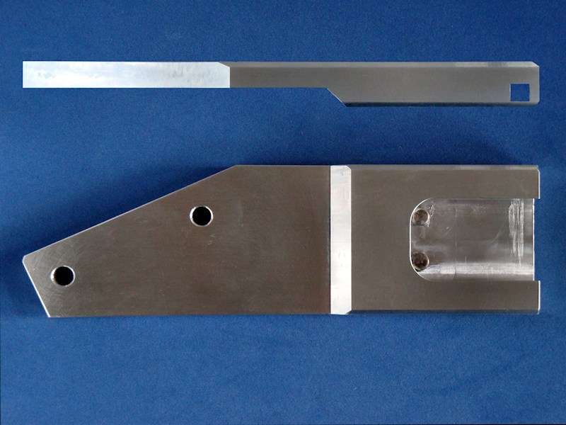 Bracket Arm.
Figure 7. |
 Bracket Arm.
Figure 8. |
|
 Emulated Mount Plate Slot.
Figure 9. |
 Assembly.
Figure 10. |
|
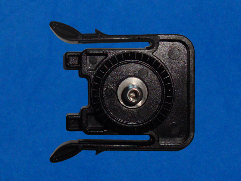 Supplied Mount Plate.
Figure 11. |
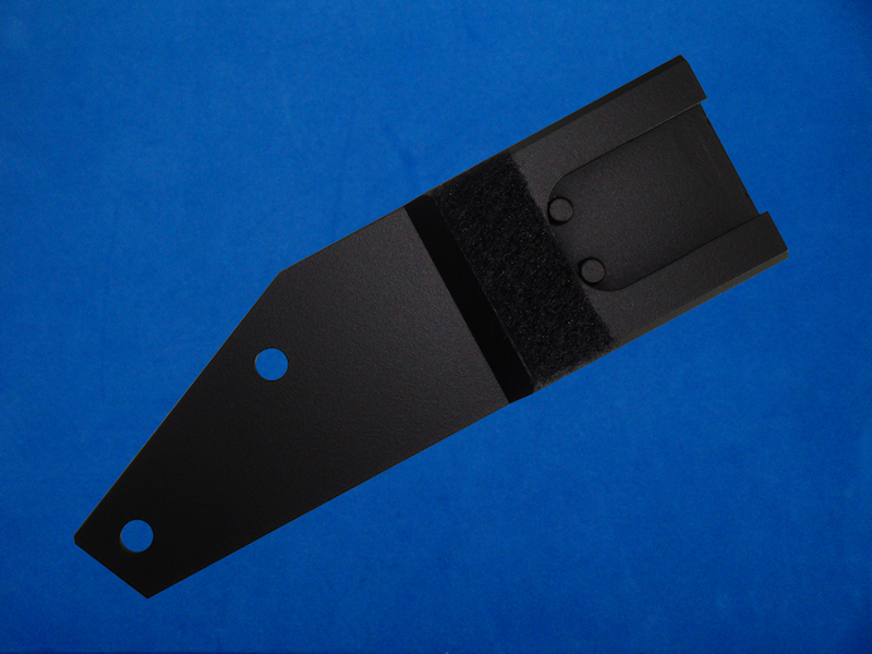 Bracket Arm Complete.
Figure 12. |
|
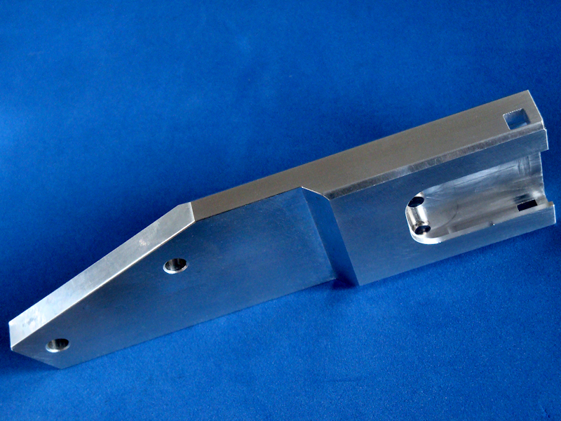
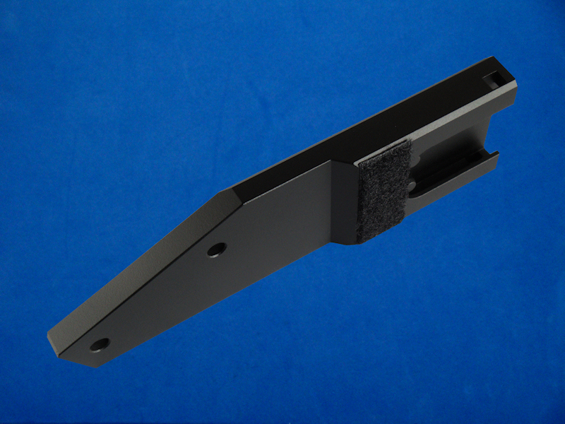 Bracket Arm Complete.
Figure 13. |
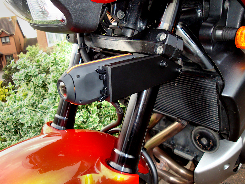 Fitted To The Bike.
Figure 14. |
Diagram 1: Fork Collar Mount Clamp Top Half. |
Diagram 2: Fork Collar Mount Clamp Bottom Half. |
Diagram 3: Camera Mount Bracket Arm. |